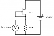
Get a 5 to 13 volt supply and a DC voltmeter. Connect the +V to the
Drain, connect the Gate and Source together to a 100 ohm resistor,
and connect the other lead of the resistor to ground.
Measure the voltage across the resistor, which gives the Idss. 1 volt
= 10 mA of current.
Try to measure all devices under the same conditions, temperature,
and duration of test.

Drain, connect the Gate and Source together to a 100 ohm resistor,
and connect the other lead of the resistor to ground.
Measure the voltage across the resistor, which gives the Idss. 1 volt
= 10 mA of current.
Try to measure all devices under the same conditions, temperature,
and duration of test.
Erno Borbely also wrote a pair of very nice articles on JFET matching, optimizing performance and it's free and on his website --
http://www.borbelyaudio.com/adobe/ae599bor.pdf
and
http://www.borbelyaudio.com/adobe/ae699bor.pdf
http://www.borbelyaudio.com/adobe/ae599bor.pdf
and
http://www.borbelyaudio.com/adobe/ae699bor.pdf
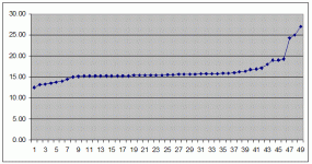
BF862 Matching result
I just bought 50 BF862's (see also the B1 Turbo on a chip thread http://www.diyaudio.com/forums/showthread.php?threadid=140488)
and the result is that at least 30 are very well matchable in pairs and even one almost perfect double quad.
You don't need to buy big numbers to get decent matching.
Rick
I just bought 50 BF862's (see also the B1 Turbo on a chip thread http://www.diyaudio.com/forums/showthread.php?threadid=140488)
and the result is that at least 30 are very well matchable in pairs and even one almost perfect double quad.
You don't need to buy big numbers to get decent matching.
An externally hosted image should be here but it was not working when we last tested it.
Rick
Attachments
Real matching may not be required. But it does not do any harm if you have both channels very close in overall Idss distribution, so do not put all 6mA Idss devices in one channel and the 12 mA devices in the other.
Close matching of the filter cap values channel to channel is also a good thing, btw..
Close matching of the filter cap values channel to channel is also a good thing, btw..
So Hannes, nothing need matching on the pearl then?
Exactly!
Of course you can do it if you want, it won't hurt.
Have fun, Hannes
Hello All
Thanks for your knowledge Much Appreciated !
Another Question.
I see that a dual supply is needed but I was gonna use the same transformer used with my AP1.7, have the 1.7 and pearl in one box and power supply in another. Supply is 30-0-30v 160VA. Yes i know its overkill but the price was right.
Should I swap for two 0-30 transformers, in which series them up and power ap1.7 and use seperately for pearl?
Cheers
Thanks for your knowledge
Much Appreciated !Another Question.
I see that a dual supply is needed but I was gonna use the same transformer used with my AP1.7, have the 1.7 and pearl in one box and power supply in another. Supply is 30-0-30v 160VA. Yes i know its overkill but the price was right.
Should I swap for two 0-30 transformers, in which series them up and power ap1.7 and use seperately for pearl?
Cheers
What really needs matching in the Pearl (as with all RIAA's ) is the equalization components. Those parts are mainly R19, R22, R23, R24, C10, C13, C11 and C12. The main concern is to match them so they are the excact same in each channel. Doing this will greatly add to the soundstage, both in width and depth. The Pearl is capable of delivering an great soundstage, if this is taken care of. The excact value is not as important as being the same between channels. Mrupp mentioned this, and I think it deserves to be repeated
You would also do good by matching at least Q8-Q11 to some degree, since they sit in //. Not really needed though, as mentioned above.
You would also do good by matching at least Q8-Q11 to some degree, since they sit in //. Not really needed though, as mentioned above.
Get a 5 to 13 volt supply and a DC voltmeter. Connect the +V to the
Drain, connect the Gate and Source together to a 100 ohm resistor,
and connect the other lead of the resistor to ground.
Measure the voltage across the resistor, which gives the Idss. 1 volt
= 10 mA of current.
Try to measure all devices under the same conditions, temperature,
and duration of test.
Mr Pass,
I know this is an old thread but would you mind checking the attached circuit to see if this is what you mean in the post regarding checking Idss?
Thanks!
Attachments
Get a 5 to 13 volt supply and a DC voltmeter. Connect the +V to the
Drain, connect the Gate and Source together to a 100 ohm resistor,
and connect the other lead of the resistor to ground.
Measure the voltage across the resistor, which gives the Idss. 1 volt
= 10 mA of current.
Try to measure all devices under the same conditions, temperature,
and duration of test.
trick question - what is voltage between gate and source , on that picture ?

ZM,
Not a trick question, only following papa's instruction as highlighted above in his message.
circuit is good , but I was (sort of ) replying on vdi_nenna's post .....
ZM,
Thanks for the confirmation. I will go rig this up.
trick question - what is voltage between gate and source , on that picture ?
I don't know. 1 volt?
- Status
- This old topic is closed. If you want to reopen this topic, contact a moderator using the "Report Post" button.
- Home
- Amplifiers
- Pass Labs
- 2SK170 matching