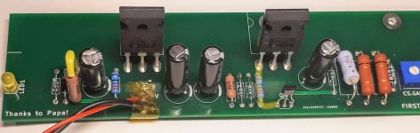
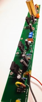
Ok, time for few pictures. The schematics and BOM I used are from this document First Watt - F3 (JeffYoung) - Google Docs, with R8 at 1.5 Ohms.
As you may notice, Q4 ZTX450 is soldered in opposite direction to the silkscreen marking on the board. It is my understanding that it's the correct way, considering that Q4s Collector has to be connected to Q3s Gate through R15, I have marked the way I see it on the picture.
As you may notice, Q4 ZTX450 is soldered in opposite direction to the silkscreen marking on the board. It is my understanding that it's the correct way, considering that Q4s Collector has to be connected to Q3s Gate through R15, I have marked the way I see it on the picture.
Attachments
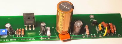
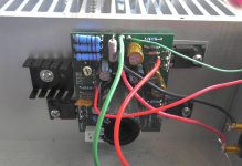
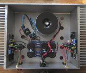
Did you connect both the power ground and the signal ground to your PSU 0 volts? (The pictures show the power ground connected, but the ground connection below the Lovoltech appears to be empty....)
Hi Jeff, thanks for replying!
the signal ground, of course
 ! For some unknown reason I have convinced myself that it doesn't have to be connected to the PSU ground. It would take me really long time to solve this one on my own. Tomorrow I will make connections and try how it works.
As for the voltages, I've meant the Source pins of Q5 and Q2, marked with 41V/3.5V on the schematic.
Cheers!
I did not, I had it clamped to a steel bar acting as a temporary heatsink, which was just not very handy for taking pictures.speaking of ....... I hope you didn't powered that without proper heatsinking
I'm about to repeat what I've done ~8 times with Rawson Amps (AJ, F5, and Gain Clone). I will soon be the 3rd owner of another Rawson build, this time what appears to the F3. I was intrigued, and these are fairly rare, plus the price was right. From the seller's pix, this is the cleanest Rawson build I've seen. But it also appears the amp will need safety earth wiring and audio ground. Since this isn't the standard PSU, I'll likely be asking questions on grounding in the future. Looks like gain and power is in the same range as my SissySIT, so this will be a fun one to try.
Attachments

All of the grounds should go back to a single point on the PSU. This minimises fluctuations on the signal reference ground from the supply ground (which will go up and down a bit with current draw variations because no wire has zero resistance).
It also allows the supply GND to be twisted with (or at least kept close to) the + and - supply wires. This minimises the chances of ground loops causing hum.
Cheers,
Jeff.
It also allows the supply GND to be twisted with (or at least kept close to) the + and - supply wires. This minimises the chances of ground loops causing hum.
Cheers,
Jeff.
All of the grounds should go back to a single point on the PSU. This minimises fluctuations on the signal reference ground from the supply ground (which will go up and down a bit with current draw variations because no wire has zero resistance).
It also allows the supply GND to be twisted with (or at least kept close to) the + and - supply wires. This minimises the chances of ground loops causing hum.
Cheers,
Jeff.
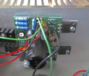
This is what I am thinking of. Just don't really get the idea of "separating signal ground from supply ground"?
The amplifier is going to amplify the difference between the input and the signal ground. Signal ground is normally 0, so it's amplifying the input.
However, if the signal ground were to float up to 0.01V, then it would be amplifying the signal minus that 0.01V. Still no big deal.
However, if the signal ground were to vary from 0 to 0.01V with the music, then it's going to result in distortion.
When the output transistors draw lots of power, that power is returning via the supply ground wire. More current through a resistance equals more voltage differential. (The wire's resistance is very low, but it's not zero. So the voltage differential will be very small, but not zero.)
If you use a different wire for the signal ground, then *that* wire is carrying very little current, and so suffers a completely negligible voltage differential. In other words, it stays at 0.
Hello,
I have some problems about the PSU, hope someone can help.
1. I have a transformer with dual 35VAC secondary instead of 18VAC, what should be the new values of R1-R10 and C1-C8?
2. Since I don't need the negative voltage for F3, should I break the lower half V+ connection to GND and connect V- to GND instead? In this case, the left/right channels can have its own PSU output. Anything wrong with this design?
Attachments
With 35V secondary, the DC voltage will be approximately 1.3 x 35V = 45.5V. It may be a bit lower.
The capacitors may be the same capacitance but the voltage rating would need to be 50V minimum.
R1 to R8 may remain the same.
The bleed resistors R9 and R10 could be doubled to 4.3K. I = 45.5V/4300R = .0106A. P= .0106A x .01016A x 4300R = 0.48W, so 3W resistor should be OK.
Yes, you can use one secondary per channel, with its own CRC filter. Each channel would have its own V+ and Gnd. Each channel should have its own Ground connected to the chassis Ground with its own thermistor. Be sure to orient the capacitors properly so that the positive is connected to R1 to R4, and that the bridge rectifier is also connected with its positive output to the capacitor positive.
- Home
- Amplifiers
- Pass Labs
- F3 Builders Thread