Hi thanh
Bateman's results are somewhat mixed, if you compare installment 5 (1uf caps tested at 1kHz) with that in installment 6 (100uF tested at 100 Hz). I think this varies a lot with frequency, package size, and individual brands. Generally the non-polar have less than half the distortion of the polar. The back-to-back polars may be better and could be worth a try, except that you need 4 times the capacitance and overall this looks somewhat “unelegant”.
Btw., another area affecting cap quality might be microphonics, and the Silmics should be very good in this respect, so overall the non-polar Silmic looks like a very attractive solution to me. Again, the question is how much of a difference does it make in the end.
P.S. I bought a local brand of non-polar caps (Frolyt) that I wanted to compare to the normal Silmics, but it might be some time before I get to do a test.
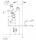
In case anyone would like the LTSpice schematic here it is.
The funny thing is I couldn't get the desired votage at the drain of the mosfet using the values from the service manual (I think it is meant to be 21V or 23V). I had to tweak some resistor values. It's not perfect but pretty close.
The funny thing is I couldn't get the desired votage at the drain of the mosfet using the values from the service manual (I think it is meant to be 21V or 23V). I had to tweak some resistor values. It's not perfect but pretty close.
Attachments
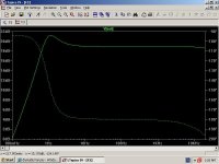
I did a frequecy response (LTSpice) using 1000uF instead of 15000uF. To me (don't trust a word I say) there doesn't seem to be an issue. There is a peak (small hump) at 1Hz which falls quickly, but other than that I can't see a problem using 1000uF instead of 15000uF.
Anyway have a look at the attachment
Anyway have a look at the attachment
Attachments
thanh, I have found that "adjusting" the model Vth lower and Beta higher, more closely approximates the devices I have and the work published by Nelson. 
I've been trying to find the time to actually measure a group of devices and "tweak" the model with the help of the "guru's" I work with. Just havent got there yet... ... ...

I've been trying to find the time to actually measure a group of devices and "tweak" the model with the help of the "guru's" I work with. Just havent got there yet... ... ...
I don't have any equipment to measure the output, but when I built my F3 with Peter's boards I used a BG N 1000/50 as my output cap (pricey, yes), but it sounds great with my Druids. The Druids are supposed to present a 12 ohm load and naturally roll off at 40-50 Hz, so my quick calc said this would be fine. Moral of the story, seeing as it's DIY, tailor it to your speakers as best you can.
Peter Daniel said:If I can suggest something for multidriver speakers, is to split the output caps between drivers and use whatever is needed only.
For instance, in my particular setup, I'm using 6.8uF Siemes MKV in tweeter network (1st order filter) and BG N 330/100 with the midrange driver (again first order filter only). No need for other big caps. If you have a woofer, then you can put 10,000uF cap there too, but it could be separated from mid/high output.
Peter,all
this sounds like an interesting concept if your talking about using both the 330uf and the 6.8uf out of the same amp.
I am not sure how your wiring it however if this is the case, if they are paralled as Nelson does it, then taking multi-taps off the + side of cap seems to make no difference.
If your using a different layout, I would like to know what it is.
I assume that C1 can only be one value, and that value determines the low filter frequency.
I would not mind some advice on how to calculate this. I am considering using it to run at 200 or 300hz on up..
Mike

Attachments
Re: Re: crossing over
AH!
So looks like (is) normal X0
So
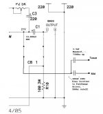
off F3 negative rail to postive speaker terminals with cap in between. Put the sucker right in front of speaker.
So polarity matters with electrolytics here, I assume + to - to + speaker terminal.
Zen Mod said:
AH!
So looks like (is) normal X0
So
off F3 negative rail to postive speaker terminals with cap in between. Put the sucker right in front of speaker.
So polarity matters with electrolytics here, I assume + to - to + speaker terminal.
Attachments
Re: Re: Re: Re: crossing over
I wont ask anymore questions......for now.
Still dont have the boards, so storing some good knowledge.
Zen Mod said:
I wont ask anymore questions......for now.
Still dont have the boards, so storing some good knowledge.
This is probably one of the best mods you can do to this amp. I was originally using Jensen 10,000/63 and it was not bad, adding 0.1uF V-Cap bypass improved high frequency clarity at the expense of naturalness, but using dedicated cap just in a tweeter network brings this amp into completely different league
Ok I am starting to get a clear picture about this mod.
I am not sure if this is the same idea you had or not.
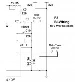
What I am thinking is running a bi-wire setup from the amp. The original out goes to bass drivers (Which run up to 2000Hz).
I then run another output before the capcitor network on the amp straight to my tweeter crossover network. Since this already has quite large capacitors in it anyway, I shouldn't need to add another cap ahead of it.
Is this the same way you did it?
I am not sure if this is the same idea you had or not.
What I am thinking is running a bi-wire setup from the amp. The original out goes to bass drivers (Which run up to 2000Hz).
I then run another output before the capcitor network on the amp straight to my tweeter crossover network. Since this already has quite large capacitors in it anyway, I shouldn't need to add another cap ahead of it.
Is this the same way you did it?
Re: Re: Re: Re: crossing over
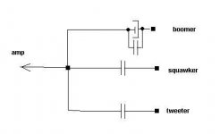
I did some potentially correct 1st order XO settings, optimized for the values I have around..
This version may work for those with a FR used as wide band, with help from WOOFER and Tweeter on top end.
This of course assumes I didn't forget something. Never used a e-cap in a crosssover, but I guess this can be thought of as part of the amp, sort of.
Thanks ZM for drawing.
T
Zen Mod said:
I did some potentially correct 1st order XO settings, optimized for the values I have around..
This version may work for those with a FR used as wide band, with help from WOOFER and Tweeter on top end.
This of course assumes I didn't forget something. Never used a e-cap in a crosssover, but I guess this can be thought of as part of the amp, sort of.
Thanks ZM for drawing.
T
Attachments
- Home
- Amplifiers
- Pass Labs
- F3 Builders Thread