Could someone give me the part number of the rectangular safety capacitor that fits Chas Sample’s power supply board for the F3. Thank you very much. Mark
The safety cap described above was sold out, I ordered the one below as a substitute, and will also be using it for C9 on the main amp boards. It has very thin leads and I'm concerned it isn't suited for line level. Could someone have a look and tell me if it's a bad idea to use this cap on the PSU board? thank you, this is my first project with a line level PSU

Blocked
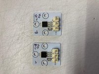
Matching R5 and Q1
Looking for confirmation if I did this right or not:
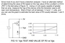
I tried measuring the Vgs using the circuit in image below and then choosing R5 based on the chart, but taking the Vgs measurement was difficult for be because the it was constantly changing with the jfet temperature. So I took my best guess at the Vgs value before the jfet got too hot and selected R5 from the chart. This didn't work well at all, my voltage at the drain of Q1 was ~2.7V (should be ~3.5).
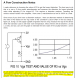
I know you solved this with a pot but I was looking at Figure 10 from the zv9 manual and it gives a different answer for a given Vgs than the chart you used. I did these measurements today on my LU1014Ds, got a Vgs of ~1.06V, and found a R5 value from Figure 10 of ~2 ohms. The R5 to Q1 chart you've posted would give an answer of 3 ohms. Just an FYI in case others run into this issue as well, and don't have power pots handy.
Attachments

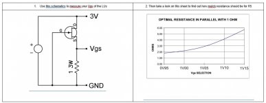
Thanks for looking into the R5 selection chart further, I would be cautious using the value from the Zen V9 chart to select R5, the Zen V9 runs 2 amp bias vs. the 1.65 amps for the F3, however Papa's note below the chart is basically what I did making the adjustment with the power resistor in place of R5, except I adjusted for the values on the F3 schematic which would give a Vds of 2.4V and a DC value of 21V so that answers my original question.
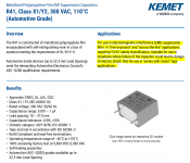
Regarding the capacitor, the one you linked to does not appear to be safety rated for "across the lines" use, look for something that meets the same safety standards as the capacitor originally specified (see datasheet from originally specified cap below).
Regarding the capacitor, the one you linked to does not appear to be safety rated for "across the lines" use, look for something that meets the same safety standards as the capacitor originally specified (see datasheet from originally specified cap below).
Attachments
The safety cap described above was sold out, I ordered the one below as a substitute, and will also be using it for C9 on the main amp boards. It has very thin leads and I'm concerned it isn't suited for line level. Could someone have a look and tell me if it's a bad idea to use this cap on the PSU board? thank you, this is my first project with a line level PSU
Blocked
The one you linked doesn't seem to be safety rated. This one should be fine:
Blocked
My connections for the potentiometer were the same as BRN's. I don't remember the exact resistor values but they were between 5 and 7 ohms and varied slightly for each channel. I made the final measurement after the amp was fully up to temperature. The setpoint of P2 also will change the DC output value slightly (approximately +/- 1.5VDC) so you will want them set the same on both channels when you are making the adjustments.
Hopefully this weekend I can get a little drill & tapping, wiring, and testing time to complete the F3 project… I really like these boards!
Very nice. I'm at a somewhat similar point, but still waiting on some parts while I puzzle out how to wire up these dual trafos.
Attachments
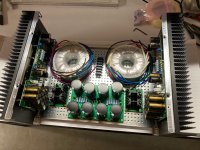
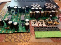
That’s a good start on a dual-mono supply.Very nice. I'm at a somewhat similar point, but still waiting on some parts while I puzzle out how to wire up these dual trafos.
Wiring one is relatively straightforward – pretty much two of everything, starting with the AC fuses. So two sets of primary wiring terminals with CL-70 thermistors, two sets of secondary bridge rectifiers, two CRC filter banks and so on.
The only thing in common between the two channels should be the safety ground to the chassis.
That’s a good start on a dual-mono supply.
Wiring one is relatively straightforward – pretty much two of everything, starting with the AC fuses. So two sets of primary wiring terminals with CL-70 thermistors, two sets of secondary bridge rectifiers, two CRC filter banks and so on.
The only thing in common between the two channels should be the safety ground to the chassis.
Yes, csample's PSU board has a thermistor in series with each trafo's (or channel's, for a single trafo) primary and two more thermistors between output ground and chassis ground. The little power-in block that comes in the diyaudio 4U build kit has provision for two AC fuses.
The tricky part for me is that these Antek AS-2218's each have two primaries at 115V and two 18V secondary windings. Per csample, I'm wiring the two secondaries of each trafo in series (no-dot end of one winding to dot end of the other winding). I decided to wire the two primaries of each trafo in parallel, downstream of the aforementioned thermistors and the line capacitor, though if this is *wrong* there is still plenty of time before power up!
Yes, wiring the 18V secondaries in series, as you described, is a way to get 36V into the bridge rectifiers. The filtered output will be the “unregulated 50V supply.” You can also read Nelson’s article on the Zen V9, which was the early non-commercial version of the F3.
Possibly fried LU1014D
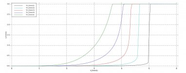
To make a long saga short, due to some failed sodering / unsoldering / resoldering / dead-bugging efforts, I think I roasted one of my LU1014Ds. My evidence for this is my attempt to replicate one of the traces in this Vd - Id plot, using the circuit of Figure 10, and varying the supply voltage from 3V to 6V.
My 'good' LU1014D looks like this:
Vsupply, 3.0, 4.0, 5.0, 6.0
Isupply, 0.85, 0.94, 1.0, 1.1
Vgs, 1.09, 1.22, 1.33, 1.43
My likely bad LU1014D looks like this:
Vsupply, 3.0, 4.0, 5.0, 6.0
Isupply, 1.05, 1.19, 1.32, 1.42
Vgs, 2.89, 3.82, 4.86, 5.81
When I first got these two parts they measured out with a Vgs of 1.06 at 3V. Now they are at the very least very different. Does the 'bad' one look bad to you? Thank you.
Attachments
- Home
- Amplifiers
- Pass Labs
- F3 Builders Thread