I replaced all the 220uf caps with Panasonic FC's, turned the P2's to minimum and mounted the lovol's to the heatsinks and it sounds so much better. I have been listening all day and it is indeed much sweeter sounding than the F5 now. I am still waiting for a couple of Mundorff's to replace the C1's.
steenoe
would you please tell what are your Impressions from Talema trt1000218 toroid
I see that you use http://www.diyaudio.com/forums/showpost.php?p=1728248&postcount=51
Is It silent toroid when loaded
I would like to buy 1 pcs of that toroid for a stereo Aleph X J
would you please tell what are your Impressions from Talema trt1000218 toroid
I see that you use http://www.diyaudio.com/forums/showpost.php?p=1728248&postcount=51
Is It silent toroid when loaded
I would like to buy 1 pcs of that toroid for a stereo Aleph X J
That's a good idea. I am fairly certain the amp functions (I've measured the output at about 12.5W into 8 ohms), though it doesn't get overly hot (well, during the summer it's scorching, but during our winter, it just stays warm).
I'll try to make time for this amp on the weekend, I've been neglecting my DIY for a few months, starting to miss it !
Hmmm ...
Going over some of my old notes while putting this thing together, the current I had going through r6|r7|r8 was about 0.5A (voltage drop of 0.2V)... That doesn't seem right ...
Hello guys,
I have a question concerning the mounting of the Lovoltech:
Can some of you post pictures how you coupled the device to the heatsink? Which materials were used???
I got through this thread, and I read clamping and "soldering". Soldering means, I solder the Lovoltech on a backside of a bigger fet mounting plate??? Which solder to use? How to prevent thermal damage...??? Peter Daniel did so - I think, I remember from another thread...
Thanks, Dirk
Thanks,
Nelsons versin pushs only on a small part of the device - I guess, with my lucky hands this will not work... ;-)
What about electrical insulation? Which parts do you use for it?
(For the normal mosfets, I will use a Glimmer pad, heat conducting paste, a screw insulator and a screw with a large washer. How much torque is recommended???
Thanks, Dirk
P.S.: Has anyone pics of good builds with Peter Daniel (Thanks for the wonderful PCB!!!) boards???
Hmmm ...
Going over some of my old notes while putting this thing together, the current I had going through r6|r7|r8 was about 0.5A (voltage drop of 0.2V)... That doesn't seem right ...
... so continuing with my own topic ... I opened up the amp last night, set my multimeter to current, put it in series with the power supply, and measured current draw, and voltage (with another multimeter).
Sure enough, it sucks up 1.6 amps, at 48V for each channel, which seems absolutely right. I hereby conclude that the power meter I'm using isn't working too well (still reads 70W, though it does detect the 500W+ my TV sucks up
 ), and that during a Melbourne winter, the heatsinks work a tad too well
 Getting Somewhere?
Since I am close to having a working amp (and I need a bit of help) I have decided to post a few pictures. A lot of this got done yesterday and I have been dying to complete the rest but inevitably I have forgotten a part. The thermistors are that one thing.
I have some unknown thermistors, only two, but more testing will have to be done to decide their suitability.
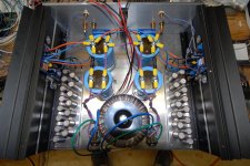
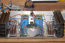
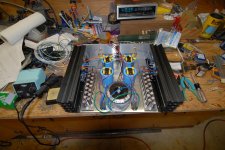
The first third and fifth pictures are overviews.
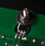
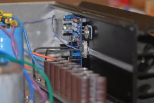
The second picture shows how I mounted Q1.
It is a sandwich: heatsink, grease, mica, grease, FET, aluminum, screws. The legs are insulated as well.
Ah yes, the output caps. I used 15x1000uf silmics
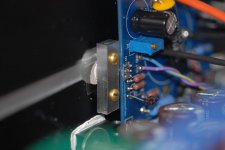
For fun I added a mounting bracket, you can see the connections in the fourth picture (black wires)
About the thermistors, can they be added before the switch without any undesirable results? How about the fuse? Also, is it critical to use one with 10 ohm start or can I use anything as long as the value evens out at temperature?
Since I am close to having a working amp (and I need a bit of help) I have decided to post a few pictures. A lot of this got done yesterday and I have been dying to complete the rest but inevitably I have forgotten a part. The thermistors are that one thing.
I have some unknown thermistors, only two, but more testing will have to be done to decide their suitability.
The first third and fifth pictures are overviews.
The second picture shows how I mounted Q1.
It is a sandwich: heatsink, grease, mica, grease, FET, aluminum, screws. The legs are insulated as well.
Ah yes, the output caps. I used 15x1000uf silmics
For fun I added a mounting bracket, you can see the connections in the fourth picture (black wires)
About the thermistors, can they be added before the switch without any undesirable results? How about the fuse? Also, is it critical to use one with 10 ohm start or can I use anything as long as the value evens out at temperature?
Attachments
Since I am close to having a working amp (and I need a bit of help) I have decided to post a few pictures. A lot of this got done yesterday and I have been dying to complete the rest but inevitably I have forgotten a part. The thermistors are that one thing.
I have some unknown thermistors, only two, but more testing will have to be done to decide their suitability.
The first third and fifth pictures are overviews.
The second picture shows how I mounted Q1.
It is a sandwich: heatsink, grease, mica, grease, FET, aluminum, screws. The legs are insulated as well.
Ah yes, the output caps. I used 15x1000uf silmics
For fun I added a mounting bracket, you can see the connections in the fourth picture (black wires)
About the thermistors, can they be added before the switch without any undesirable results? How about the fuse? Also, is it critical to use one with 10 ohm start or can I use anything as long as the value evens out at temperature?
Very nice! Where did you get those heatsinks?
Yes, see post #166 and a few after for the rest of the story.Papa heatsink....
About the thermistors, can they be added before the switch without any undesirable results? How about the fuse? Also, is it critical to use one with 10 ohm start or can I use anything as long as the value evens out at temperature?
I found some 5 Ohm thermistors at HSC, will these work if I use two in series? One? 0-THERMISTOR 5 OHM 3D7113-HSC Electronic Supply
I am really pulling to get this up and running by sunday.
Hi guys,
My F3 has left virtual universe and is now in the building stage.
But i have a fundamental question/dilema:
I'd like to make all 220u/63v Elna Silks - but can't find them, lower voltages are easy.
So i'm looking towards Rubycon ZL/Nichikon KZ/Panasonic FC ?
I do have already Nichicon VZs but don't know how suitable they are !?
I'd value an opinion here...or a source for the silks.
One other question: I notice NP uses 50V caps, so clearly it's enough for the original, is it enough for the clone ?
Are the supply rails the same in the clone ?
...questions questions...
Last edited:
CeeVee,
You can get whatever you need from "Handmade Audio" in Pennsylvania, USA - he has a wide range of both Nichicon and Silmics - his costs are quite good and delivery excellent.
Also, these caps are often available on the "eBay" in small quantities, and I think "audiograde" (eBay, USA) may have some.
The difference between Silmics and Nichicons in position C5 is quite startling, and if you're using PDs pcbs, that C5 is right on the edge and can quite easily have a bipass "tacked on" underneath - if you want to have a bit of fun, add an RC network across the C5 (a 1.5R resistor in series with a 220uF/63v Rifa peg124 cap, etc) instead of the usual 1uf or, 0.1 uF, film cap - or none at all!
It's a real PIA that these caps take so long to settle down to their final sound - the Rifas are as slow as the BGs and the Siemens (Epcos) not much better! At least the KZs and Silmics are fairly quick, in comparison.
If you're not confident that your rail voltage won't exceed 50 volts, then yes, perhaps use the higher voltage caps for C5, C7 and maybe also C6 - the rest can be 25 volt ones, including the C1, which makes a Siemens/Epcos (or BGs)a more reasonable price if you want to go that far.
Then there's also Matt Cambell at Audio Capacitors (see Vendors List here) for other good caps - the F&Ts sound "same as" Mundorfs, "similar to" Jensens, etc, etc as p.supply caps, anyway.
It's definitely worth using a good quality wire for this amp - it's an often neglected component.
All the best ....
- Home
- Amplifiers
- Pass Labs
- F3 Builders Thread