S500 Biasing Question
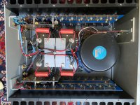
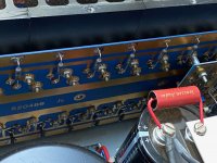
I have an S500 Series II (not optical bias) that I've done a bit of work on. Replaced power supply caps with 4 large 33,000uf caps (Epcos were all I could find) and added 4 Jantzen 0.47uf coupling caps as talked about on Threshold Lovers (pics attached). Now I'd like to bias the amp. I spent a few hours downloading and reading the posts on this topic, schematics and specs. But I still have a few admittedly dumb questions. First, there are two trim pots on each channel. Is one for DC Offset? Which one is for bias. One has a metal screw coming out of it, the other pot has a white plastic screw on its side. (pic). Does any one know which is bias? Second, as I understand the process, you connect a Mmeter clip to one of the output resistors at the middle top of each channel, and the neg clip goes into the neg rail fuse on the back? Can anyone confirm? —Thx.
I have an S500 Series II (not optical bias) that I've done a bit of work on. Replaced power supply caps with 4 large 33,000uf caps (Epcos were all I could find) and added 4 Jantzen 0.47uf coupling caps as talked about on Threshold Lovers (pics attached). Now I'd like to bias the amp. I spent a few hours downloading and reading the posts on this topic, schematics and specs. But I still have a few admittedly dumb questions. First, there are two trim pots on each channel. Is one for DC Offset? Which one is for bias. One has a metal screw coming out of it, the other pot has a white plastic screw on its side. (pic). Does any one know which is bias? Second, as I understand the process, you connect a Mmeter clip to one of the output resistors at the middle top of each channel, and the neg clip goes into the neg rail fuse on the back? Can anyone confirm? —Thx.
Attachments
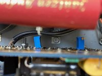
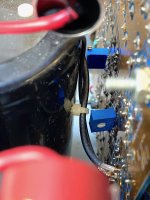
Yes, one will be offset, the other is bias. I looked at the schematic on the first page and it is very similar to the Stasis 2, and there wasn't a factory offset, so I am going to guess the single turn white center adjust unit is the bias, and someone has added the multiturn pot for offset in place of the fixed 300R in the first stage (bottom left corner of schematic). If that is the original single turn bias pot, you may want to put in a new one, or a multiturn as those would become flakey over the years. One way to measure current is to remove the rail fuse and just clip on either side of the rail fuse holder, then just carefully twiddle one pot to see if it changes bias or offset. Not sure what the S500 is supposed to be biased at but should be somewhere in this forum. If you look at the schematic on the first page, it indicates 20-30mV across a 1R emitter resistor, and if you take that .02-.03A current, and multiply it by 9 output devices you have 180mA -270mA idle current range, if I am interpreting the schematic correctly. Check the heatsink temp after an hour warmup, you should be able to hold you hand on it comfortably, or if you have a IR temp gun, around 50C.
Good luck.
Cheers
Good luck.
Cheers
Last edited:
Thanks for the quick response Kilohertz. So to confirm your suggestion on question 2, I should attach multimeter to output resistor and other end of mm to the neg fuse holder. I think that is what you are saying. Yes, agreed, I need to change these pots. I'm in the Bay Area and near Pass resources and may seek some help.
Thank you.
Thank you.
Sorry missed this last Q 3 days ago.
If you want to measure voltage and figure out the current from that, then yes you can measure from one end of an emitter R, the end that connects to the transistor, and the other end on one of the rail fuses. If you want to measure live total bias current, then remove the rail fuse and clip the mm to either end of the fuse holder, your meter then makes the circuit complete and measures actual total bias current (with a negligible amount that the front end consumes).
Cheers
- Status
- This old topic is closed. If you want to reopen this topic, contact a moderator using the "Report Post" button.