Hi Nelson
If it is not an indiscretion, i would like to learn about the method you are using to submit single and balanced inputs.
A balanced input is implemented by a subtractor etc, etc, to convert a symmetrical signal in single ended.
In your projects as i suppose, you are passing also the single input from the subtractor, by grounding its negative input with a link in the XLR socket ( Vo = V+in - V-in) and thus the output of subtractor it is the same single input signal.
I know this method from my expertise in pro audio mixing desks.
Am i right untill now?
In Bryston manuals, i have seen a different approach. There is a discrette devices composed input operational amplifier, which with the aid of a 6P-DT switch, can operate or as a subtractor for balanced signals, or as a non inverting amplifier (with a little gain) for single input signals.
Regardless of which is your approach in your projects, which is the better method of the two?
I am in the process of building a preamplifier (if you remember, you have seen photos of my pcbs in solid state) and i am confused which of the two methods is better (by taking into account also the cost and the complexity of input circuitry) for my case?
Are you satisfied from your method of grounding the -input of the subtractor for single input signals?
Why Bryston don't uses the same and simplest method as you?
The same method as yours i had also me in my mind.
Can you give me a little help in my choice?
Thanks in advance
Fotios
fotios said:A balanced input is implemented by a subtractor etc, etc, to convert a symmetrical signal in single ended.
This is not necessarily true. Our amplifiers do not make a balanced
to single-ended conversion - their outputs are balanced.
Also, the amplifiers are not opamps. They are much closer to devices
like the THS4131 from Texas Instruments. Two inverting gain stages
are operated with local feedback but are also cross-coupled to each
other so that each feeds its error signal to the other, creating an
error cancellation at both outputs.
They accept ground as a legitimate input without loss of performance.
Having said that, the Aleph amplifiers had an "op amp" topology
with balanced inputs which were also happy operating balanced or
unbalanced. You can see an example and explanation of this
approach in the A75 articles at www.passdiy.com

Re: Re: One question mr. Pass about balanced inputs
Nelson
Thanks a lot for your politeness to give me these precious informations.
This IC of Texas THS41xx it is an amazing stuff!! Not so for its top slew rate, but for its +/-Vcc acceptance. Maybe i am not informed so deeply, but i haven't seen never an IC with so high supply level, of +/-33Vdc!! Amazing!
Looking further, i have started to perceive your approach in your symmetrical designs in power amplifiers as well in your preamps. Very smart!
From those that i understand - by looking also in A75 app. - instead the conventional way of driving one voltage gain stage from the collector of the transistor of LTP looking the input, or from the collectors of the same transistors in the case of double LTPs which drives two voltage gain stages (symmetrical approach) for each half of signal (although i am using simple LTP in my projects from experiments i know very well that the double LTPs which drives symmetrical voltage gain stages can give a far better slew rate), the drive signal for the opposite V.G.S. received from the collector of the transistor of LTP looking the output.
Thus, in the case of single input signal, simply the feedback node it is grounded (as usually in conventional designs) but the single signal it is converted simultaneously in two opposite symmetrical signals. Instead in the case of symmetrical input signals, the inverted signal it is coupled directly to the base of the transistor looking the feedback. This is correct, because in either of the two cases, the polarity of the signal it is appropriate to drive the opposite V.G.S. (i like this expression more than the common known VAS ).
I have seen the same approach of driving two symmetrical V.G.S. but from single LTP in input of amplifiers implemented with BJTs. One meaningfull remark, it is that there is not any miller compensation capacitor in the V.G.S. in such type symmetrical designs.
I don't know if my thoughts are correct at whole, so i ask your forgiveness for any nonsense thought exists.
Thanks again for your lights.
Fotios
Nelson Pass said:
This is not necessarily true. Our amplifiers do not make a balanced
to single-ended conversion - their outputs are balanced.
Also, the amplifiers are not opamps. They are much closer to devices
like the THS4131 from Texas Instruments. Two inverting gain stages
are operated with local feedback but are also cross-coupled to each
other so that each feeds its error signal to the other, creating an
error cancellation at both outputs.
They accept ground as a legitimate input without loss of performance.
Having said that, the Aleph amplifiers had an "op amp" topology
with balanced inputs which were also happy operating balanced or
unbalanced. You can see an example and explanation of this
approach in the A75 articles at www.passdiy.com
Nelson
Thanks a lot for your politeness to give me these precious informations.
This IC of Texas THS41xx it is an amazing stuff!! Not so for its top slew rate, but for its +/-Vcc acceptance. Maybe i am not informed so deeply, but i haven't seen never an IC with so high supply level, of +/-33Vdc!! Amazing!
Looking further, i have started to perceive your approach in your symmetrical designs in power amplifiers as well in your preamps. Very smart!
From those that i understand - by looking also in A75 app. - instead the conventional way of driving one voltage gain stage from the collector of the transistor of LTP looking the input, or from the collectors of the same transistors in the case of double LTPs which drives two voltage gain stages (symmetrical approach) for each half of signal (although i am using simple LTP in my projects from experiments i know very well that the double LTPs which drives symmetrical voltage gain stages can give a far better slew rate), the drive signal for the opposite V.G.S. received from the collector of the transistor of LTP looking the output.
Thus, in the case of single input signal, simply the feedback node it is grounded (as usually in conventional designs) but the single signal it is converted simultaneously in two opposite symmetrical signals. Instead in the case of symmetrical input signals, the inverted signal it is coupled directly to the base of the transistor looking the feedback. This is correct, because in either of the two cases, the polarity of the signal it is appropriate to drive the opposite V.G.S. (i like this expression more than the common known VAS
).I have seen the same approach of driving two symmetrical V.G.S. but from single LTP in input of amplifiers implemented with BJTs. One meaningfull remark, it is that there is not any miller compensation capacitor in the V.G.S. in such type symmetrical designs.
I don't know if my thoughts are correct at whole, so i ask your forgiveness for any nonsense thought exists.
Thanks again for your lights.
Fotios
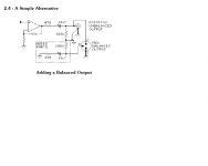
or convert all your unbalanced outputs to pseudo balanced using the Jensen Fig2.4 circuit from AN003.
Jensen suggest upgrading the balanced output by reducing the Rs values to 100r and increasing the coupling caps to Panasonic ece-a1cn221s 220uF bi-polar 16V electrolytics.
They also warn against using any of the TL06x, TL07x and TL08x opamps to drive these interconnects.
Jensen suggest upgrading the balanced output by reducing the Rs values to 100r and increasing the coupling caps to Panasonic ece-a1cn221s 220uF bi-polar 16V electrolytics.
They also warn against using any of the TL06x, TL07x and TL08x opamps to drive these interconnects.
Attachments
AndrewT said:or convert all your unbalanced outputs to pseudo balanced using the Jensen Fig2.4 circuit from AN003.
They also warn against using any of the TL06x, TL07x and TL08x opamps to drive these interconnects.
This was also covered in the A75 article. I wonder why they warn against
TL07x, etc.?
AndrewT said:or convert all your unbalanced outputs to pseudo balanced using the Jensen Fig2.4 circuit from AN003.
Jensen suggest upgrading the balanced output by reducing the Rs values to 100r and increasing the coupling caps to Panasonic ece-a1cn221s 220uF bi-polar 16V electrolytics.
They also warn against using any of the TL06x, TL07x and TL08x opamps to drive these interconnects.
Hi Andrew
Glad to see you here. Many thanks for your very informating post, although my question to Nelson has the reverse direction; how we can merge one balanced and one single (unbalanced) input in the same amplifier module and not how we can obtain one single and one balanced output from the same module (without the use of two modules - follower and inverter).
Fotios
I am confused with the term single ended
Nelson
I looked in fast some of the articles included in Pass Labs diy.
I am confused with the term "single ended solid state amplifier". From those that i know, this term reffered in amplifiers which are not using a push-pull output stage. A push -pull stage as we know, usually implemented from complementary transistors (in the past when there was not reliable power PNP transistors, as we know, they used only NPN output transistors in semi-complementary arrangement) and there is the need of a split power supply for operating. From the other hand, i know the early editions of amplifiers in which used a single power supply - i mean only +Vcc; is this type - in which used single and not split supply - the named single ended?
I apologise for my ignorance, but you see that i am little younger from you (me i am 50 years old, and you as i think from your recent photo quoted bellow, between 55 to 60 ). Of course i am kidding!
Fotios
Nelson
I looked in fast some of the articles included in Pass Labs diy.
I am confused with the term "single ended solid state amplifier". From those that i know, this term reffered in amplifiers which are not using a push-pull output stage. A push -pull stage as we know, usually implemented from complementary transistors (in the past when there was not reliable power PNP transistors, as we know, they used only NPN output transistors in semi-complementary arrangement) and there is the need of a split power supply for operating. From the other hand, i know the early editions of amplifiers in which used a single power supply - i mean only +Vcc; is this type - in which used single and not split supply - the named single ended?
I apologise for my ignorance, but you see that i am little younger from you
(me i am 50 years old, and you as i think from your recent photo quoted bellow, between 55 to 60 ). Of course i am kidding!Fotios
Attachments

fotios said:
how we can merge one balanced and one single (unbalanced) input
in the same amplifier module ...
Fotios
you mean,
construct a (pre-)amplifier input
that in a good way accept BOTH balanced & un-balanced signal sources
.. and regardless delivers a 'normal' unbalanced output
what is the best way to do this?
how do we deal with the voltage gain in both cases?
One LTP pair input.
Or Two 'complementary' LTP pairs.
And so we must consider how to arrange global feedback, if we want to use this.
Well, myself never use any balanced inputs.
Because I have no need for this in any of my applications.
Not even for signal from TurnTable to Phono RIAA
or signal from Microphones.
I prefer to amplify my very tiny signals, BEFORE they are sent to pre-amplifier/voltage amplifier.
This way using un-balanced RCA cable of good audio quality is well enough.
I have not found any use for cancel out noise/distortion of same polarity.
As is one idea of balancing transfer of small signals.

lineup said:
you mean,
construct a (pre-)amplifier input
that in a good way accept BOTH balanced & un-balanced signal sources
.. and regardless delivers a 'normal' unbalanced output
what is the best way to do this?
how do we deal with the voltage gain in both cases?
One LTP pair input.
Or Two 'complementary' LTP pairs.
And so we must consider how to arrange global feedback, if we want to use this.
Well, myself never use any balanced inputs.
Because I have no need for this in any of my applications.
Not even for signal from TurnTable to Phono RIAA
or signal from Microphones.
I prefer to amplify my very tiny signals, BEFORE they are sent to pre-amplifier/voltage amplifier.
This way using un-balanced RCA cable of good audio quality is well enough.
I have not found any use for cancel out noise/distortion of same polarity.
As is one idea of balancing transfer of small signals.
Hi Lineup
Glad to see also you here. In reality - and from my 25 years expertise with pro-audio - i agree with you for the non use of balanced in/outs in domestic appliances. In microphones of which the signal runs through a 15 to 20 meters cable up to the mixing desk yes.
I don't understand why the constructors of Hi-End devices they turned in the use of balanced signals. To subtract noise? From a signal cable of 1,5m length? No. Simply to add more gain (i mean bigger headroom)? Maybe yes.
I have two friends which have SACDs - from those includes XLR outputs - and they are stay to hear their expensive players from their balanced outputs. What can i do further?
Oh! this greedy people! this unsatisfied people!
Fotios
The subject it is about the volume control
The problem in reality it is found in the volume control. What i mean:
Let us to say that we have a stereo preamp. with balanced and single inputs, as well balanced and single outputs.
You are right in that you said. There is no need for conversion from balanced to single if we use seperate amplifiers for the non-inverting and for the inverting input as input buffers. Simply, for a stereo device we need 4 seperate input buffers (amplifiers). The problem it is that there is the need of use a 4 gang volume pot. before the 4 output buffers. Then, the stereo balanced signals can run in 4 seperate rails from input to output.
As for the single (unbalanced) signals, these can run only in the non-inverting rail of each channel from input to ouput. In this case also, there is the need of grounding the inverting inputs to avoid noise caused if these are open circuited.
Unfortunatelly, in my preamplifier i had not made a such prediction and i bought two motorized dual gang ALPS. To use them, now i am forced for double conversions. One from balanced to single in the balanced inputs before the volume pot. and again a single to balanced convertion after the pot. so as i can have one balanced output. That is the double work! GRRRRR!!!

I think to finish my project with only single in/outs
Fotios
Nelson Pass said:
This is not necessarily true. Our amplifiers do not make a balanced
to single-ended conversion - their outputs are balanced.
The problem in reality it is found in the volume control. What i mean:
Let us to say that we have a stereo preamp. with balanced and single inputs, as well balanced and single outputs.
You are right in that you said. There is no need for conversion from balanced to single if we use seperate amplifiers for the non-inverting and for the inverting input as input buffers. Simply, for a stereo device we need 4 seperate input buffers (amplifiers). The problem it is that there is the need of use a 4 gang volume pot. before the 4 output buffers. Then, the stereo balanced signals can run in 4 seperate rails from input to output.
As for the single (unbalanced) signals, these can run only in the non-inverting rail of each channel from input to ouput. In this case also, there is the need of grounding the inverting inputs to avoid noise caused if these are open circuited.
Unfortunatelly, in my preamplifier i had not made a such prediction and i bought two motorized dual gang ALPS. To use them, now i am forced for double conversions. One from balanced to single in the balanced inputs before the volume pot. and again a single to balanced convertion after the pot. so as i can have one balanced output. That is the double work! GRRRRR!!!
I think to finish my project with only single in/outs
Fotios
mcs (www.dantimax.dk) have all sorts of motorized and non motorized pots - at fair prices
Re: The subject it is about the volume control
A pair of matched variable resistors is all that is needed.
The variable resistor is connected from hot to cold after an accurately matched line resistor in each feed.
you do not need 4 matched pots to volume control a stereo balanced signal.fotios said:
The problem in reality it is found in the volume control. What i mean:
Let us to say that we have a stereo preamp. with balanced and single inputs, as well balanced and single outputs.
You are right in that you said. There is no need for conversion from balanced to single if we use separate amplifiers for the non-inverting and for the inverting input as input buffers. Simply, for a stereo device we need 4 separate input buffers (amplifiers). The problem it is that there is the need of use a 4 gang volume pot. before the 4 output buffers. Then, the stereo balanced signals can run in 4 separate rails from input to output.
A pair of matched variable resistors is all that is needed.
The variable resistor is connected from hot to cold after an accurately matched line resistor in each feed.
- Status
- This old topic is closed. If you want to reopen this topic, contact a moderator using the "Report Post" button.
- Home
- Amplifiers
- Pass Labs
- One question mr. Pass about balanced inputs