I have another question that will showcase my lack of knowledge if someone wants to help me to understand ") .
.
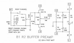
I'm assuming V+/V- is ~ 20VDC/0VDC; is the purpose of R3 and R4 to form a divider which creates separate but equal +/- rails with reference to ground? If I got that correct , I'm going to celebrate with a glass of red!!!
. I'm assuming V+/V- is ~ 20VDC/0VDC; is the purpose of R3 and R4 to form a divider which creates separate but equal +/- rails with reference to ground? If I got that correct , I'm going to celebrate with a glass of red!!!
It's a little early for a drink, but it's 5 O'clock somewhere
you're close, maybe the words you typed were a little off ....
"is the purpose of R3 and R4 to form a divider which creates separate but equal +/- rails to create a floating zero volts between the + / -?"
you're close, maybe the words you typed were a little off ....
"is the purpose of R3 and R4 to form a divider which creates separate but equal +/- rails to create a floating zero volts between the + / -?"
Last edited:
I'm away in the Arctic(work), and on nightshift. It's always 5:00 when I'm off the clock, lol.
I think we are trying to express the same idea. Sometimes it's easier to build the circuit to understand it. I wish I was home.
Why is it called floating (does this particular common connection avoid the chassis)?
Edit: For the sake of complete clarity on my part(ignoring losses), is the basic idea to have:
D+ ~ +10V(potential difference of 10VDC to 20VDC)
D- ~ -10VDC(potential difference between 10VDC to 0VDC)?
- Tim
I think we are trying to express the same idea. Sometimes it's easier to build the circuit to understand it. I wish I was home
. Why is it called floating (does this particular common connection avoid the chassis)?
Edit: For the sake of complete clarity on my part(ignoring losses), is the basic idea to have:
D+ ~ +10V(potential difference of 10VDC to 20VDC)
D- ~ -10VDC(potential difference between 10VDC to 0VDC)?
- Tim
Last edited:
Floating, because it floats
It's not in common with anything.
Your PSU should be isolated from everything else on the planet, as a smps power brick is.
The smps has a Neg and a Pos (these are floating because they are isolated - except in relation to each other). You are just making a point in the center. When you connect the 0v center (floating,, virtual- whatever) to your audio ground - now it is ground.
It is what you want it to be.
Now the stage is set for the +10 to be 10v above ground and the -10 to be -10v below ground.
There is a kook here that says ground is a state of mind. We're not talking about EARTH here!
Last edited:
Autoformer Volume Control With B1?
Hi everyone - long-time lurker with a random question. Has anyone used the Slagle autoformers in place of the pots for the B1's volume control??
I have a pair of the slagles that I've wired up as a pure passive preamp. However, I ran across the following blurb about Vinnie Rossi's autoformer implementation:
LIO Integrated Amplifier - Vinnie Rossi Audio
It seems like a B1 with the autoformer modules could achieve something similar... I'd love your thoughts on this! Regardless, it sounds like a fun experiment =)
Hi everyone - long-time lurker with a random question. Has anyone used the Slagle autoformers in place of the pots for the B1's volume control??
I have a pair of the slagles that I've wired up as a pure passive preamp. However, I ran across the following blurb about Vinnie Rossi's autoformer implementation:
The LIO AVC/Tubestage combo module combines our highly transparent autoformer attenuator with our seductive sounding Tubestage buffer to create a reference-level linestage that combines the best sonic attributes of both – true synergy at play! The AVCs are hand-wound by David Slagle of Intact Audio. They simply sound more open, transparent, detailed, and dynamic than any other volume control available. Following this with our LIO Tubestage built onto the same module (keeping the signal path as short as possible) adds more tonal density and a larger soundstage into the equation. The Tubestage features Class-A operation, auto-biasing, constant-current tube filament supply, precision voltage regulation, and other tweaks that make this a super low noise, high performance design that is exceeded in performance only by our Directly Heated Triode (DHT PRE) linestage. The result is a winning combination of high precision with the spaciousness and lifelike character that tubes are known for.
LIO Integrated Amplifier - Vinnie Rossi Audio
It seems like a B1 with the autoformer modules could achieve something similar... I'd love your thoughts on this! Regardless, it sounds like a fun experiment =)

Your PSU should be isolated from everything else on the planet, as a smps power brick is.
Best to check, I have seen ones where they connect to AC Earth.
Hi everyone - long-time lurker with a random question. Has anyone used the Slagle autoformers in place of the pots for the B1's volume control??
I have a pair of the slagles that I've wired up as a pure passive preamp. However, I ran across the following blurb about Vinnie Rossi's autoformer implementation:
LIO Integrated Amplifier - Vinnie Rossi Audio
It seems like a B1 with the autoformer modules could achieve something similar... I'd love your thoughts on this! Regardless, it sounds like a fun experiment =)
i have the older custom made slagle autoformer as a volume pot and output of the B1 at 39r
sounds great. before i use the autoformer as passive pre and it rolled off highs and lows.
I believe/hope you used B1 feeding AVC , not the other way?
i use the aVC in place of the volume pot on the B1 board. Am i doing it wrong?
It's not in common with anything......There is a kook here that says ground is a state of mind. We're not talking about EARTH here!
Understood
. Thanks for taking the time! Are there many instances in amplifiers where the PE, and the audio ground don't share the chassis in common? I've seen lifted audio grounds, etc. But they always end up at the chassis...?
Most of the circuits(systems) I work with are referenced to a common ground( Airframe). At my current employer, I don't get to work inside the boxes though. That's all outsourced to bench shops...
Having built a B1 in 2009 with the original circuit and PCB I have just noticed the revised 2014 R2 schematic. Would someone please explain or point me to a discussion about this revise. Thanks.
Attachments
Last edited:
Disclosure: I am probably the least qualified person on this forum to answer your question. In the spirit of SNL, I'm going to "chime-in" anyways! and hope someone corrects me (maybe I can learn something from the experience too ) .
1) I believe that C X01 & R X04 in Ver. 1 were deleted to allow for a DC offset adjustment that didn't put a capacitor in the audio path.
2) RX02 had the described purpose of preventing parasitic oscillation. Seeing that it is removed, I'm guessing it was an "extra" safety net, for a "just in case" situation. It was potentially removed to simplify the signal path from the most likely low voltage source.
3) C X00 I don't fully understand the purpose. My best guess is that they were blocking the audio signal from the "1/2 source" bias voltage from the PSU section to the base of the transistors. *Sorry, Gate. I think that the voltage divider at R X03/X04 probably accomplishes this now.
I'll start with that and see where I stand. Others, please feel free to critique and point out my errors. Hopefully I am in the ballpark, or at least playing the right sport
) . 1) I believe that C X01 & R X04 in Ver. 1 were deleted to allow for a DC offset adjustment that didn't put a capacitor in the audio path.
2) RX02 had the described purpose of preventing parasitic oscillation. Seeing that it is removed, I'm guessing it was an "extra" safety net, for a "just in case" situation. It was potentially removed to simplify the signal path from the most likely low voltage source.
3) C X00 I don't fully understand the purpose. My best guess is that they were blocking the audio signal from the "1/2 source" bias voltage from the PSU section to the base of the transistors. *Sorry, Gate. I think that the voltage divider at R X03/X04 probably accomplishes this now.
I'll start with that and see where I stand. Others, please feel free to critique and point out my errors. Hopefully I am in the ballpark, or at least playing the right sport
Last edited:
Having built a B1 in 2009 with the original circuit and PCB I have just noticed the revised 2014 R2 schematic. Would someone please explain or point me to a discussion about this revise. Thanks.
Original b1 is single ended, b1 rev2 is push pull using a complimentary and much harder to get pair of jfets. Also it has dual polarity psu which lets you get rid of the coupling caps in rev1.
I have built both although rev2 had a much bigger and better psu and better pot. They sound totally different. Rev1 sounded like what I expected. Very tame and nice. Rev2 is totally ruthless and revealing in both good and bad ways.
I don’t use buffers...it was just an test so neither stayed in my system. But with the F5 amp I felt like the rev2 version was just too revealing and hard although it was amazing at what it did and initially I had a big smile on my face.
I loaned both to a friend with big emotiva amps and he felt the same way.
With a different amp/speaker combo your results might be different.
- Home
- Amplifiers
- Pass Labs
- B1 Buffer Preamp