Grounding question
I did it.
I built my own B1.
In principle it works, but I have a 50Hz hum.
If I hook up the input with the pot it is only faintly audible, but if I disconnect the B1 input and let it float it is very pronounced.
Given the huge input impedance of the B1, I can see that I built a real nice noise receiver. But the thing that strikes me is that the hum goes away, if I connect the signal ground to the chassis ground - I did that accidentally.
Now the question, where can I improve?
I have the power mains come into the chassis via a regular fused IEC/C14-connector. From there I run a grounding cable to the chassis. Both live wires pass through a switch and go to a 24V SMPS.
The B1 is fed from the COM and V+ terminals of the SMPS.
The amp is in the same box and also floats against chassis ground. I can not measure a finite resistance between chassis ground and signal ground.
So, what can I do?
100nF btn chassis and signal ground already quench the hum. But somehow I have the impression that this solution is uncool. Where does the hum actually get into the system?
Hints appreciated.
The B1 is a buffer.
It converts a higher output impedance to a lower output impedance.
It is ideal for driving interconnects from a source that cannot already do that adequately.
eg, a CD player that has Rs=2k or an ipod that has a current limit of 2mA, or an attenuator that has a variable output resistance that varies from 0r1 to 12k5.
Put the buffer at the source.
In general the power amp input does not need a buffer.
Locating a buffer with the power amp is defeating the purpose of a buffer.
The only exception that comes to mind is an electronically balanced input (but badly designed) where the -IN impedance is very much lower than the +IN impedance. Here a buffer can equalise the input impedances to get the balanced connection working as designed.
Well... I am building an integrated amp, if you like.
The purpose of the buffer is to have the amp see the same impedance after the volume pot.
May I come back to my original grounding question?
I could add that all power cables are twisted pairs, so are the connectors btn B1 and amp. I built the filter section separate from the genuine buffer section with input and output caps and the JFETs. Between the two I have very short leads that I already shortened with no effect.
touching the plastic cases of the input caps affects the hum.
piccie
Here ya go, schematic drawing of my setup.
The parts on the boards are roughly drawn how I assembled the protoboards for the filter and buffer. I did the wiring of the boards with enameled wire.
All the wavy lines are twisted AWG 23 CAT5 wire.
I can break the loop in front of the input of the amp as indicated in the schematic. Only it changes nothing.
The only thing that does help is to tie the signal ground to the chassis ground.
Attachments
Just Finished my B1
Hi Guys,
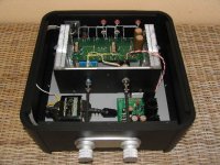
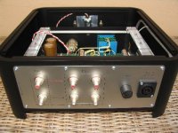
Very good information on this thread, I also have built my B1, I’ve used the board sold by Nelson pass, and then implemented my own ideas for component usage, the list it’s quite interesting:
- Fully aluminum body, painted in black powder finish, with solid aluminum knobs, front plate, and black plate with all imprints.
- CMC silver RCA plugs, Neutrik 32A mains plug (the best), and gold plated Bulgin fuse holder.
- All signal internal cabling is Mundorf M-Wire, 99% silver + 1% gold + HGC monofilament pure silver wire covered in pure Teflon sleeve.
- All power cabling from Nordost.
- Input selector from ELMA.
- Volume control based on a Shalco type 41 positions selector, with military SMD low noise resistors – 10K linear type.
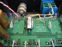
- Input resistors Caddock TF020 + Caddock MP130 in other positions. Some PRP, and one MILLS power resistor.
- Signal Caps are V-CAP (the best).
- Filtering caps are Nichicon MUSE gold (> 25.000uF).
- Power transformer is 50VA! R-Core.
- Power Supply based on a discrete Mosfet regulated design, with MUR820 rectifiers.
Sound? Absolutely wonderful. My SF Guarnieri has come to life again!
More photos will follow.
Hi Guys,
Very good information on this thread, I also have built my B1, I’ve used the board sold by Nelson pass, and then implemented my own ideas for component usage, the list it’s quite interesting:
- Fully aluminum body, painted in black powder finish, with solid aluminum knobs, front plate, and black plate with all imprints.
- CMC silver RCA plugs, Neutrik 32A mains plug (the best), and gold plated Bulgin fuse holder.
- All signal internal cabling is Mundorf M-Wire, 99% silver + 1% gold + HGC monofilament pure silver wire covered in pure Teflon sleeve.
- All power cabling from Nordost.
- Input selector from ELMA.
- Volume control based on a Shalco type 41 positions selector, with military SMD low noise resistors – 10K linear type.
- Input resistors Caddock TF020 + Caddock MP130 in other positions. Some PRP, and one MILLS power resistor.
- Signal Caps are V-CAP (the best).
- Filtering caps are Nichicon MUSE gold (> 25.000uF).
- Power transformer is 50VA! R-Core.
- Power Supply based on a discrete Mosfet regulated design, with MUR820 rectifiers.
Sound? Absolutely wonderful. My SF Guarnieri has come to life again!
More photos will follow.
Attachments
Well, V-caps are new to me, B1 is working since 2 days ago, and they do need quite a big breaking time, nevertheless when I compare with clarity caps (as is), I fill they are much, much better (my opinion), very clear and very much like no cap at all. Duelund, never tryed them
many thanks on your kind remarks!
many thanks on your kind remarks!
Re: Just Finished my B1
Nice build. Which one is your regulator? Series or shunt?
rclourenco said:- Power Supply based on a discrete Mosfet regulated design, with MUR820 rectifiers.
Nice build. Which one is your regulator? Series or shunt?
Dobs said:Wow, superb!!
Did you made the case or you bought it?
Bought it at www.hexateq.com
sheers!
Nelson Pass said:Wowie Zowie!

Well, coming from the Master, I really thank you for the answer.
Re: Re: Just Finished my B1
All-discrete topology
Single-pass, series regulator design.
No IC (integrated circuits) are used. This allows complete design control over all operating points and parameters for superior performance.
Low noise, high PSRR
A constant-current source feeds a zener diode as a stable voltage reference. A low-pass filter (with a corner frequency of 1.6Hz) prevents zener noise from being introduced into the error amplifier. This is an effective yet lower-cost alternative to expensive voltage reference ICs. The low-pass filter also provides a soft-start characteristic.
The output noise (unloaded) is less than 12µV (measured using a Tangent LNMP (low-noise measurement preamplifier) and a Fluke 187 50000-count DMM in ACmV mode). This is several times lower than the noise of an IC regulator based PSU tested under identical conditions.
The error amplifier is a discrete implementation of an opamp with a high open-loop gain of 102.5dB. The voltage supply to the error amplifier is isolated with capacitance multipliers to boost its PSRR (power supply rejection ratio). This greatly improves the line regulation performance of the PSU.
A long-tailed pair differential amplifier with current mirror and constant current source forms the first stage of the error amplifier. The second stage is the voltage amplification stage (VAS), also with constant current source load. The 3rd stage is comprised of the power MOSFET output devices configured as a source follower.
High-current MOSFET pass transistors
Two paralleled high-current, highly reliable MOSFETs (rated at 18A each) serve as the "pass" transistor.
The high current rating provides a very high safety headroom against overcurrent damage.
The use of paralleled MOSFETs divides the heat dissipation, simplifying thermal management. Onboard heatsinks can be used which would allow the to supply up to 1A continuous (with much higher peak currents). More sustained currents are possible by using larger, offboard heatsinks.
The negative temperature coefficient of MOSFETs prevents damaging thermal-runaway conditions that may plague conventional BJT devices.
from: www.amb.org
Salas said:
Nice build. Which one is your regulator? Series or shunt?
All-discrete topology
Single-pass, series regulator design.
No IC (integrated circuits) are used. This allows complete design control over all operating points and parameters for superior performance.
Low noise, high PSRR
A constant-current source feeds a zener diode as a stable voltage reference. A low-pass filter (with a corner frequency of 1.6Hz) prevents zener noise from being introduced into the error amplifier. This is an effective yet lower-cost alternative to expensive voltage reference ICs. The low-pass filter also provides a soft-start characteristic.
The output noise (unloaded) is less than 12µV (measured using a Tangent LNMP (low-noise measurement preamplifier) and a Fluke 187 50000-count DMM in ACmV mode). This is several times lower than the noise of an IC regulator based PSU tested under identical conditions.
The error amplifier is a discrete implementation of an opamp with a high open-loop gain of 102.5dB. The voltage supply to the error amplifier is isolated with capacitance multipliers to boost its PSRR (power supply rejection ratio). This greatly improves the line regulation performance of the PSU.
A long-tailed pair differential amplifier with current mirror and constant current source forms the first stage of the error amplifier. The second stage is the voltage amplification stage (VAS), also with constant current source load. The 3rd stage is comprised of the power MOSFET output devices configured as a source follower.
High-current MOSFET pass transistors
Two paralleled high-current, highly reliable MOSFETs (rated at 18A each) serve as the "pass" transistor.
The high current rating provides a very high safety headroom against overcurrent damage.
The use of paralleled MOSFETs divides the heat dissipation, simplifying thermal management. Onboard heatsinks can be used which would allow the to supply up to 1A continuous (with much higher peak currents). More sustained currents are possible by using larger, offboard heatsinks.
The negative temperature coefficient of MOSFETs prevents damaging thermal-runaway conditions that may plague conventional BJT devices.
from: www.amb.org
- Home
- Amplifiers
- Pass Labs
- B1 Buffer Preamp