Problem with my B1 buffer(s)
Hello
i just finished a prototype for a cross over circuit using B1 buffers. I build every thing on Perf board. I checked the circuit over and over but there seems to be a shortcut between the +9V and -9V rails (that is also what i can measure with my multimeter). What could be the problem?
The only components that can cause a shortcut between the +9V and -9V rails are the 2sk170. Are the broken? But i made 6 PCB with every PCB 4 buffers (symmetrical signal) and on every PCB i have the shortcut
My 2SK170 are connected like this
1) first 2sk170:
- Gate to input
- Source to drain of second 2sk170
- Drain to +9V
2) second 2sk170
- Gate and Source to -9V
- Drain to source of first 2sk170 --> connects to PLLXO network.
Any ideas?
....
Any ideas?
High resolution pictures of both sides of perfboards would help.

Hello Nelson,
yep i checked that (also with the 2sk170 datasheet) and i don't see any mistakes. But it takes some time to dissasemble. I will post a picture of one buffer circuit after that.
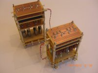
This is how it looks like, but you can't see the details in this picture:
B1-PLLXO (HP or LP)-B1-attenuator-B1.
regards,
Harold
yep i checked that (also with the 2sk170 datasheet) and i don't see any mistakes. But it takes some time to dissasemble. I will post a picture of one buffer circuit after that.
This is how it looks like, but you can't see the details in this picture:
B1-PLLXO (HP or LP)-B1-attenuator-B1.
regards,
Harold
Attachments
I found two problems:
1) I found a short cut in one of the 2sk170 legs and corrected it
2) In the first buffer of the HP i found a resistor of 1K iso 1M to ground, stupid mistake. I had to take out the board because one of the jfets was burned. I now use the 1st buffer of the LP to also drive the HP filter.
Now i have sound coming from the system on a very low volume for the Hp and no sound from the LP. Before I build in the buffers, i checked the PLLXO with visual analyser for the correct filter frequency and everything worked fine.
Some more research into the circuit to find out what could be the cause of this issue
regards
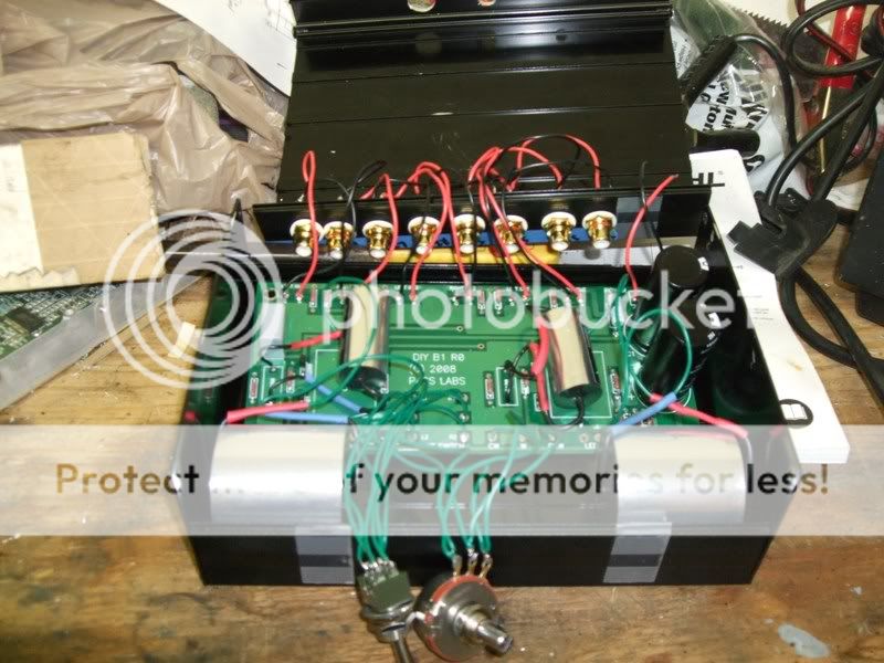
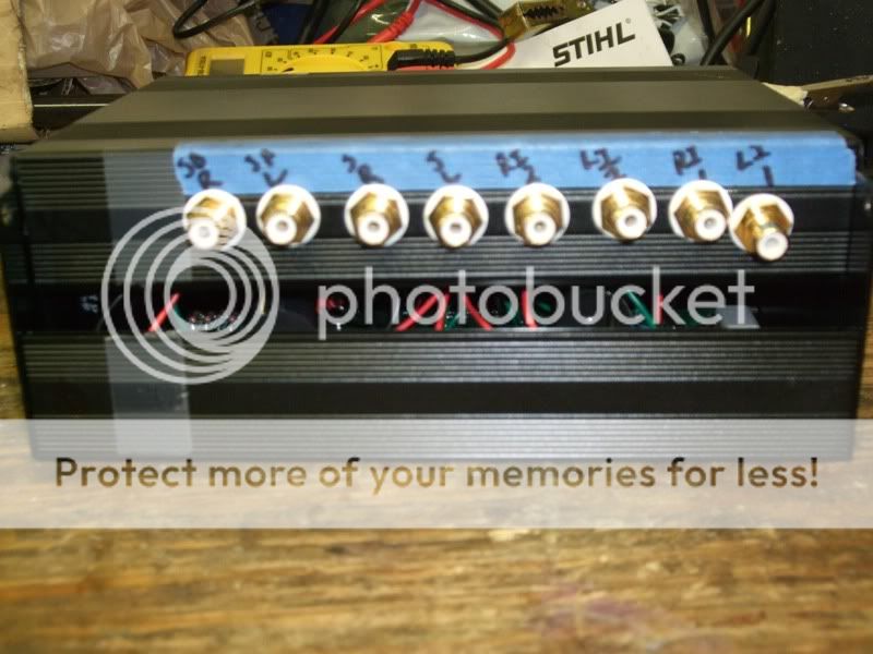
Well I got some more done today. I made a few mistakes on this project but I do not think anything will impact the performance. I made the hole for the switch a little too big and drilled one hole for an RCA at a bad angle. The RCA is tilting down because on the inside of the cover it is hitting a rib piece. I should be able to somehow file it down so it will be flat but it is also a little off center compared to the other.
Now all I need it to get the power receptacle (back order at this time), solder in the led and get a knob for the volume pot.
The picture just shows the PCB laying ion the housing, I have not secured it at this time, just wanted to take a picture real quick.
James
Now all I need it to get the power receptacle (back order at this time), solder in the led and get a knob for the volume pot.
The picture just shows the PCB laying ion the housing, I have not secured it at this time, just wanted to take a picture real quick.
James
I am currently using my B1 with two PP9 batteries strapped in series to give 18v and am very pleased with the results. I wonder if the sound will go off as the voltage drops; although its only dropped 1v after a couple of months. Would I be better off using a regulated supply something like a Super Teddy reg which I see severall people have used. Has anybody tried both and come down in favour of one or the other. Any advice would be appreciated.
Marra.
Marra.
9V Batteries in Series
I've been doing the same (two 9V Batteries in series) and didn't notice much of a change even after it had dropped down to 14V (i.e. 7V each).
Just last weekend started running it off an old 20V Dell laptop adapter for convenience sake. Some performance hit in Sound Quality and wondering if it's possible to tweak it in some way. Suggestions welcome!
I am currently using my B1 with two PP9 batteries strapped in series to give 18v and am very pleased with the results. I wonder if the sound will go off as the voltage drops; although its only dropped 1v after a couple of months. Would I be better off using a regulated supply something like a Super Teddy reg which I see severall people have used. Has anybody tried both and come down in favour of one or the other. Any advice would be appreciated.
Marra.
I've been doing the same (two 9V Batteries in series) and didn't notice much of a change even after it had dropped down to 14V (i.e. 7V each).
Just last weekend started running it off an old 20V Dell laptop adapter for convenience sake. Some performance hit in Sound Quality and wondering if it's possible to tweak it in some way. Suggestions welcome!
Yes I started out using a lap top supply then tried batteries which I thought was a step up. Guess I'm just going to have to build a regulated supply and check it out; I have transformer; rectifier and caps and sockets; just hoped some one would post there thought on Teddy regs etc. Has anyone by any chance tried out the Avondale Audio TPX pcb's?
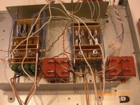
I have been listening to the prototype of my crossover for some hours now. It is a little grainy (i think) but the caps propably need some time. There is no hum, noise whatsoever even without any signal on it, only at max volume when i am close to the speakers. I am now wondering how to add Baffle Step Correction to the circuit.
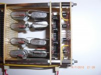
Volume control is done per channel for left and right with grayhill 12 position switches (MBB) in shunt configuration, so only 1 resistor in the signal path. The volume steps are now in 3db, i think i will change that later to 1.5db or 1db.
The system is modular, so i can exchange the frequency module for HP and LP. Current setting is 2200Hz. My other speakers require 3000Hz.
The filters now are second order per + and - signal, giving in effect a 4th order filter. I will also try this with 1st order filters (in effect second order on a balanced signal setup).
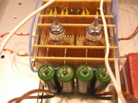
All Caps are russian. The filter caps are silver mica's I had to put them in parallel to get the correct values. The output caps are Paper in Oil. 10uF for the LP (the big brown ones) and 1uF for the HP (green ones).
PSU via 2 rechargable 9.6V (2300mAH) tamiya racing packs.
Everything is build on an old onkyo cd player chassis. In the end i will build a full aluminium chassis. A 46 step volume control from my current passive pre amp will be added as well as a rotary input selector (direct or relais).
I am also looking for a discrete circuit for SE to balanced conversion, otherwise transformers (expensive).
I will keep you updated on the sound (improvement)
Volume control is done per channel for left and right with grayhill 12 position switches (MBB) in shunt configuration, so only 1 resistor in the signal path. The volume steps are now in 3db, i think i will change that later to 1.5db or 1db.
The system is modular, so i can exchange the frequency module for HP and LP. Current setting is 2200Hz. My other speakers require 3000Hz.
The filters now are second order per + and - signal, giving in effect a 4th order filter. I will also try this with 1st order filters (in effect second order on a balanced signal setup).
All Caps are russian. The filter caps are silver mica's I had to put them in parallel to get the correct values. The output caps are Paper in Oil. 10uF for the LP (the big brown ones) and 1uF for the HP (green ones).
PSU via 2 rechargable 9.6V (2300mAH) tamiya racing packs.
Everything is build on an old onkyo cd player chassis. In the end i will build a full aluminium chassis. A 46 step volume control from my current passive pre amp will be added as well as a rotary input selector (direct or relais).
I am also looking for a discrete circuit for SE to balanced conversion, otherwise transformers (expensive).
I will keep you updated on the sound (improvement)
Attachments
- Home
- Amplifiers
- Pass Labs
- B1 Buffer Preamp