In mean time I think I realize why P type is more degenerated.
If Vgs of output Fairchilds is different by 2V, like in your comparison PDF, then drain loads of Jfets (trimpots) is very different to compensate for offset.
With this example Mr. Pass told us, that if cannot to match, we can to tweak circuit.
If Vgs of output Fairchilds is different by 2V, like in your comparison PDF, then drain loads of Jfets (trimpots) is very different to compensate for offset.
With this example Mr. Pass told us, that if cannot to match, we can to tweak circuit.
This has not been published before.
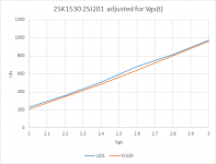
Here are the Toshibas -- adjusted for the slight difference in Vgs(t) with Vds of 20V
Attachments

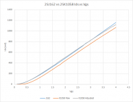
Here are the Renesas devices -- well known that yfs is lower, and thermal behavior opposite the vertical mosfets. to more accurately carry out this analysis you need a pulsed test fixture. The slopes are within 4%
I didn't select a degeneration resistor with any purpose in mind other than to refrain from blowing the fuses on my DM511.
I didn't select a degeneration resistor with any purpose in mind other than to refrain from blowing the fuses on my DM511.
Attachments
Probably because the F5 was designed from the beginning to be a DIY effort...a amp to get people started building amps.
Also, if the output is shorted bad things can happen quick on a f5. That is primarily the function of the protection. It's a current limiter only. No DC protection. Theoretically if the amp never pushes over 5A (I believe that is the current limit) it shouldn't effect the circuit in any way. It's mostly to keep the amp from smoking if the outputs are shorted, it's not really speaker protection.
Thanks Hikary, actually I was aware that the protection circuit is indeed a current limiter and not a dc protection. Still it sounded strange not to have it in other amps. Now I understand from what you wrote that it is the "easiness " with which the f5 can deliver high current that ask for the current limiting feature. Thanks again
> the Fairchilds gm matched up better
If you were referring to the original FQA19N20C / FQA12P20 then I cannot disagree more.
.
Here are the fairchild devices. the slopes differ by ~6% -- I regressed the data starting with 100mA
How do the measurements of the FQAs by EUVL and jackinnj reconcile?
How do the measurements of the FQAs by EUVL and jackinnj reconcile?
Could be that Patrick mounted his devices on a different type of heat sink. Best observation would be with the heatsinks at the same temperature and with a pulsed test fixture. I can do this with my FG5010 and wait until the heat sink temperature has reached stasis.
I don't know whether a 1R or 047R resistor was used in Patrick's example.
Note that the Fairchild curves pull away from each other in both cases.
The Toshibas seem to match up best.
We use a computer controlled aluminium heater block weighing some 5kg, with extra thermal insulation on all outer surfaces.
It has a thermal time constant of multiple hours, and takes 6 hours to heat up before any measurements.
The current sensing resistor has a tempco of < 30ppm, sitting on a separate heatink at room temperature.
The data acquisition ADC's have an accuracy of <0.2% and are additionally calibrated against a HP multimeter.
We don't use pulse mode.
We run the FET continuously until the computer registers a repeatability of 0.5% over the complete range.
2000 data points are taken and then fitted with a 6th order polynomial to remove noise.
The curves we showed are pure Id vs. Vgs and do not include any source resistor.
Patrick
Last edited:
We use a computer controlled aluminium heater block weighing some 5kg, with extra thermal insulation on all outer surfaces.
It has a thermal time constant of multiple hours, and takes 6 hours to heat up before any measurements.
The current sensing resistor has a tempco of < 30ppm, sitting on a separate heatink at room temperature.
The data acquisition ADC's have an accuracy of <0.2% and are additionally calibrated against a HP multimeter.
We don't use pulse mode.
We run the FET continuously until the computer registers a repeatability of 0.5% over the complete range.
2000 data points are taken and then fitted with a 6th order polynomial to remove noise.
The curves we showed are pure Id vs. Vgs and do not include any source resistor.
Patrick
Phew!!!


Nothing quite as good a "half way measures"! </humor>
That's some set up there.
I'm tired just thinking about what is/was involved in setting that up!
Not enough coffee or tea...
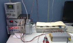
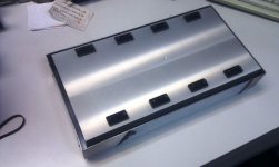
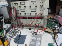
Pictures of our matching setup, MOSFET heater block (insulation removed), and a special heater block for TO92 JFETs.
And the FET tester of our own design.
Patrick
.
And the FET tester of our own design.
Patrick
.
Attachments
hi, any help is welcome
My recent build of the F5 has this simptoms:
Cold start - bias rises to 0.7v on both channels and stays there for 3 to 5 seconds and then go low to 0.60v after a while. this voltage is my bias setup after thermal equilibrium (1 hour) but i have flutuation between 0.595v and 0.625v
my dc offset is stable on both channels at 1mv
i have little hum on the speaker when i have my ear very very close. This hum seems to be related to the hum or noise i have inside the case near the rectifier bridge. I have the ixys diode and they get really hot. i can't touch them more than 2-3 seconds
https://www.digikey.pt/product-search/en?keywords=DPG60C200QB-ND
thank you.
nothing connected to the input. i am going to do the bias procedure again with the inputs shorted. My problem here is the inrush at cold start. Is it a common behavior?
so, it is normal the noise (mechanical?) inside the case?
if i can't reduce hum with wire arrangement, what else can be done?
thank you
so, it is normal the noise (mechanical?) inside the case?
if i can't reduce hum with wire arrangement, what else can be done?
thank you
nothing connected to the input. i am going to do the bias procedure again with the inputs shorted. My problem here is the inrush at cold start. Is it a common behavior?
Do you have thermistor in series with transformator?
so, it is normal the noise (mechanical?) inside the case?
Big toroids can buzz a bit. It helps to have 2 separate rectifier bridges...
It is normal for bias to start off little higher and back off as the thermistors start reducing the gate drive once the amp warms up.
It is normal for diodes to run hot. A heatsink is absolutely needed as the standing current is pretty high. You can expect about a watt for every ampere of standing current through the diodes, which makes them run hot. Add to that the temperature inside the case, and they could be quite toasty. If your fingers are not blistering, it's under 80 degrees which is okay for the diode, if not your fingertips.
It is normal for diodes to run hot. A heatsink is absolutely needed as the standing current is pretty high. You can expect about a watt for every ampere of standing current through the diodes, which makes them run hot. Add to that the temperature inside the case, and they could be quite toasty. If your fingers are not blistering, it's under 80 degrees which is okay for the diode, if not your fingertips.
Try turning the transformer a bit and re-tighten.(Not too tight.)
Try some rubber or cork sheet under the transformer.
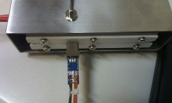
By the way, nice tidy build.
A suggestion from my troubles.
Take the power from the rectifier board via connector blocks to the amp boards.
Then you can take one out of circuit without de soldering wires.
Try some rubber or cork sheet under the transformer.
By the way, nice tidy build.
A suggestion from my troubles.
Take the power from the rectifier board via connector blocks to the amp boards.
Then you can take one out of circuit without de soldering wires.
Last edited:
- Home
- Amplifiers
- Pass Labs
- F5 power amplifier