The 100mm up for the lower row of mosFETs looks about right. 100:430 = ~23%Thank you, Zen Mod.
Both pcbs doesn't fit in one line, how much vertical distance should I keep between them?
Size of the heat sink is 270 x 430 mm
I would suggest 100 and 200mm off the ground, is this ok? Or should I put it more upwards with more distance to each other?
View attachment 459496
Thanks for your patience with an noob
The upper row @ 200mm seems a bit too low. ~47%. aim for between 55% and 65%. Try 260mm up from the bottom.
There is a bit of free software that will let you experiment with placement to determine the layout that gets all the devices to the same Tc and same Ts at the interface area.
Not much difference between Rin = 50k or 100k.The original F5 design showed 1K +100K input impedance. Later this was changed to 4.7K+ 47K. Recently at a DAC comparison a similar setup (dac/preamp) to mine sounded dread-full, which we contributed to the fact that the tube-amp in use at that day had a 12K input impedance. The suspicion being that this low input impedance was the cullpit.
My question is what the advantage/disadvantage of using the +/-50K or 100K input impedance and why was the change made to the original design?
Very big difference between 50k and 12k.
Looking back from the Receiver:
The amp sees The series elements of the input filters and the shunt elements of the input filters in parallel with Rin and also in parallel with the parasitics of the input cable and now the most important part also in parallel to the output impedance of the Source. That Source could be a vol pot or a Buffer or a ready made component (eg. CDP).
The low Source impedance (Rs) dominates what the Receiver sees as it's input load.
A high value series filter adds to that Rs.
All Receivers have a preferred Source impedance. BUT unfortunately this is rarely specified. D.Self has published some guidance for his power amplifiers' preferred input impedance. His recent writings are suggesting <100r and certainly <<1k
Few power amplifiers meet this requirement of low source impedance. Very large RF shunting capacitors at the input to a power amplifier help in getting the HF source impedance down to low levels. This is something that has been mentioned by many designers over the decades. I typically use 680pF or 1nF as the last element before the +IN pin. Recently in view of D.Self, I changed this to 2n2F (allowing the 1k series resistor to be reduced to 300r) and so far have not noticed any downside to the rescaling of the RF filter.
One needs to look at the whole input connection from Source to Receiver to make any sensible suggestions. Stating 12k, 50k & 100k does not get close to allowing analysis of the input connection.
Thanks, I have a passive pre-amp, consisting of a shunt pot with 2.5K series and 10K pot to ground. The DAC out has got 32R I/V resistance.
Intresting you mention the Source impedance, do we know what would be the prefered Source impedance for the F5 design?
One more question. Would the F5 be suitable to drive a 16Ohm speaker?
The original F5 design showed 1K +100K input impedance. Later this was changed to 4.7K+ 47K. Recently at a DAC comparison a similar setup (dac/preamp) to mine sounded dread-full, which we contributed to the fact that the tube-amp in use at that day had a 12K input impedance. The suspicion being that this low input impedance was the cullpit.
My question is what the advantage/disadvantage of using the +/-50K or 100K input impedance and why was the change made to the original design?
DAC>>Preamp>>F5?
Make sure that there is no DC on the output of the preamp. This would bias the input JFETs. When a tube circuit is switched on, for a moment (a very brief moment) the sending end of the capacitor is HIGH and approximates zero by the e^-t/rc equation. If the output capacitor leaks, or there's dirt on the pcb or internal wiring you could have enough mV to effect the operation of the input JFETs.
BTW -- in their low noise differential amplifiers (7A22N, 5A22N) Tektronix allowed the user to discharge the capacitor with a pushbutton.
I don't recall a recommended value for Rs...................
Intresting you mention the Source impedance, do we know what would be the prefered Source impedance for the F5 design?.................
Keeping it low is usually not a problem.
Adopting a 2k5 + 10k pot leaves you with a variable Rs of 0r0 to 3k125
that falls into the categories of very low Rs to very high Rs.
Well, thanks to the fine folks here in the Pass forum on DIYAudio, my son's F5 is (nearly) done. Done enough to post pix, at least .
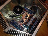
Many bumps along the way; but it's humming right along, puttin' out heat, and playing beautiful music. Unfortunately when I say "humming" I mean it literally, of the 60hz variety. We reduced the hum quite a bit by replacing the coax input wires seen in the photos with twisted pairs routed along the bottom plate, but a faint hum is still present when a source, or just RCA cables, are connected to the inputs. The amp is dead silent when the inputs are shorted.
Here's how I'm thinking of dealing with the hum, in ascending order of difficulty:
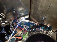
1: Rotate the toroids to move the secondary leads further away from the amp boards. Would require lengthening the secondary and primary leads.
>Q: Could the little wire stubs from the unused secondaries be causing problems? would cutting them flush help?
2: Install a ground loop breaker per the instructions on the ESP Audio Pages.
3: Install an EMF shield around the toroids.
>Q: Ferrous or non-ferrous? I.e., is the EMF noise primarily electrostatic or magnetic, or something else? From reading other posts it sounds like magnetic fields from a toroid are negligible...
4: Change the topography of the rear plate so that the input and output connectors are close to the left and right edges of the plate, and the IEC & switch are in the middle, so the output wires and more importantly input wires have a more direct path to the connectors, and reducing their proximity to the toroids, secondary leads, and PSU board.
5: Put PSU in separate housing (last resort to be avoided at all costs).
Your thoughts are greatly valued, as usual. Sorry for the low-quality pics... I'll try to take some shots with better lighting & will post them to the Pass pictures thread.
(PS: Before anyone asks, yes the MOSFETS are insulated. Only had TO-220 sized sil-pads but they fully cover the metal pad on the FETS with some overlap. Tested for continuity and they're OK. Will replace with larger insulators later)
.Many bumps along the way; but it's humming right along, puttin' out heat, and playing beautiful music. Unfortunately when I say "humming" I mean it literally, of the 60hz variety. We reduced the hum quite a bit by replacing the coax input wires seen in the photos with twisted pairs routed along the bottom plate, but a faint hum is still present when a source, or just RCA cables, are connected to the inputs. The amp is dead silent when the inputs are shorted.
Here's how I'm thinking of dealing with the hum, in ascending order of difficulty:
1: Rotate the toroids to move the secondary leads further away from the amp boards. Would require lengthening the secondary and primary leads.
>Q: Could the little wire stubs from the unused secondaries be causing problems? would cutting them flush help?
2: Install a ground loop breaker per the instructions on the ESP Audio Pages.
3: Install an EMF shield around the toroids.
>Q: Ferrous or non-ferrous? I.e., is the EMF noise primarily electrostatic or magnetic, or something else? From reading other posts it sounds like magnetic fields from a toroid are negligible...
4: Change the topography of the rear plate so that the input and output connectors are close to the left and right edges of the plate, and the IEC & switch are in the middle, so the output wires and more importantly input wires have a more direct path to the connectors, and reducing their proximity to the toroids, secondary leads, and PSU board.
5: Put PSU in separate housing (last resort to be avoided at all costs).
Your thoughts are greatly valued, as usual. Sorry for the low-quality pics... I'll try to take some shots with better lighting & will post them to the Pass pictures thread.
(PS: Before anyone asks, yes the MOSFETS are insulated. Only had TO-220 sized sil-pads but they fully cover the metal pad on the FETS with some overlap. Tested for continuity and they're OK. Will replace with larger insulators later)
Attachments
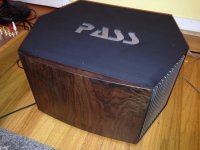
That thing looks awesome!
You already have a ground-breaker, it's the CL-60 from PSU gnd to chassis.
First thing to try is rotating the transformers. Loosen the bolt and twist them as much as you can and see if you can make it better, or worse. Better is of course preferable.
Get the input and output wires away from the transformers and up against the chassis walls.
You have confirmed that it does not hum when the input or inputs are shorted.
What does the hum and noise measure?
Does it hum when one input cable is attached? Measurement?
Does it hum when the remote end of that cable is shorted? Measurement?
Does adding a second cable change the hum? Measurement?
Does shorting the remote end of the second cable change the hum? Measurement?
Does shorting the two remote ends of the shields together change the hum? Measurement?
Turn it off. Let caps discharge. Put little stickers on ground points on boards and chassis. Get two alligator clips attached by maybe 1ft wire. Turn on amp. Attach alligator clip to one of the ground points. Touch other clip to each of marked points. This is easy way to find a quick solution. Also touch and move all ground wires. This can expose improper placement of wire or solder joint that needs touch up.
Hi
My F5 fuse keeps burning up right after turning on.
I've done as Zen Mod suggested: broke PSU rails from PCB and using 100W bulb measured around 11 VDC btw + and –
It’s a 1.25A fuse for both channels, mains is 220V
Does that sound right?
Any suggestions where to look for next?
Thank you all.
IK
My F5 fuse keeps burning up right after turning on.
I've done as Zen Mod suggested: broke PSU rails from PCB and using 100W bulb measured around 11 VDC btw + and –
It’s a 1.25A fuse for both channels, mains is 220V
Does that sound right?
Any suggestions where to look for next?
Thank you all.
IK
What are you describing?broke PSU rails from PCB and using 100W bulb
Do you mean you have disconnected the amplifier from the PSU and now you are powering up the PSU alone through a primary located Mains Bulb Tester?
One Question regarding the "periphery" of the Amp.
I see a lot of amps build with all the things like dc-protection and anti-plop-whatever...
On the other hand there are some builds without that stuff, that have the amp outputs connected directly to the terminals.
Since I have an eye on too much (preventable) contact resistance between amp and speaker I even think about soldering the speaker wires directly to the pcbs. I definitly don't want to have an relais contact in this line if I don't need it necessarily
Assuming the Amp is in good biased condition, working with no problems...
How does the f5 behave? Will I hear some "plopp" when turning on and off?
PSU is already build with an 500VA toroid transformer followed by CRC (30mF, 0,1 Ohm and 40mF on each side)
What I've seen by testing the psu (or actually didn't see anymore, cause the lights went out ) is the need for an soft start
I see a lot of amps build with all the things like dc-protection and anti-plop-whatever...
On the other hand there are some builds without that stuff, that have the amp outputs connected directly to the terminals.
Since I have an eye on too much (preventable) contact resistance between amp and speaker I even think about soldering the speaker wires directly to the pcbs. I definitly don't want to have an relais contact in this line if I don't need it necessarily
Assuming the Amp is in good biased condition, working with no problems...
How does the f5 behave? Will I hear some "plopp" when turning on and off?
PSU is already build with an 500VA toroid transformer followed by CRC (30mF, 0,1 Ohm and 40mF on each side)
What I've seen by testing the psu (or actually didn't see anymore, cause the lights went out
) is the need for an soft startTo avoid things like relay's in-line with the output, you can force a short with a relay, intending to save the speakers by blowing an output fuse or burning the output FETs...Since I have an eye on too much (preventable) contact resistance between amp and speaker I even think about soldering the speaker wires directly to the pcbs. I definitly don't want to have an relais contact in this line if I don't need it necessarily...
...What I've seen by testing the psu (or actually didn't see anymore, cause the lights went out
That way, the relay is out of the circuit unless a shutdown action is triggered.CL-60's in the mains work quite well for turn on surge protection
Hi
My F5 fuse keeps burning up right after turning on.
I've done as Zen Mod suggested: broke PSU rails from PCB and using 100W bulb measured around 11 VDC btw + and –
It’s a 1.25A fuse for both channels, mains is 220V
Does that sound right?
Any suggestions where to look for next?
Thank you all.
IK
do the bulb light up?
Assuming the Amp is in good biased condition, working with no problems...
How does the f5 behave? Will I hear some "plopp" when turning on and off?
I usually don't have plops and so on with push-pull amps. Only the Single Ended amps do plop. My F5 and F5Tv3 both don't plop....
Walter
Last edited:
- Home
- Amplifiers
- Pass Labs
- F5 power amplifier