I learned so many things.
THAT is exactly what DIY audio is all about -- it has has an extra bonus of a nice amplifier when you are all done learning.


desolder Jfets
check them as explained earlier
check every passive component
turn pots in one way , measure
turn them in other way , measure
things are logical , if you go sistematically
you don't need to understand entire picture , but you need to understand smaller pieces
and , please , when citing voltages , make difference between voltage at ( in most cases referenced to gnd .... then you need to specify exact node ) and voltage across part
I think the pot got me crazy. I thought it worked cause in two positions I have two values (0 ohm and 60 ohm). But measuring it at serveral positions I have always 60 ohm. Infact after the same turns (P1 and P2) I have 500 ohm and 60 ohm. With 3 V and -0.5 V
And the two jfet rise to 22V and 12 V.
I'll try a new pot.
And the two jfet rise to 22V and 12 V.
I'll try a new pot.
There is no excuse for a broken or non operating adjustment pot after powering up an F5.turn pots in one way , measure
turn them in other way , measure
The set up procedure BEFORE applying power is: to SET the TWO pots to ZERO ohms and to check that by MEASURING the resistance while adjusting. The third pot, if fitted, gets set to mid resistance. Again you MEASURE, to confirm that the pot is adjusting.
This set up procedure guarantees that the POT is WORKING before powering up with the Mains Bulb Tester.
There is no excuse for a broken or non operating adjustment pot after powering up an F5.
The set up procedure BEFORE applying power is: to SET the TWO pots to ZERO ohms and to check that by MEASURING the resistance while adjusting. The third pot, if fitted, gets set to mid resistance. Again you MEASURE, to confirm that the pot is adjusting.
This set up procedure guarantees that the POT is WORKING before powering up with the Mains Bulb Tester.
At first I made two measurements and the resistance changed, but it rises up only to 60 ohm...
To confirm this I have to desolder the pot...
I have a bias stability problem on F5 on one channel only. When the volume of my pre.amp is low then there no problem. When it goes up bias voltage (on 47 ohm) increases dramatically. Temperature of mosfets and 47 ohm resistors rising over 100C in very shot time and start to smoke I have extremely large heat sings also 4k7 NTC installed.
Problem is on the left channel only.. Rigth one is rock solid. Bias voltage which was set to 0.60v and measured temperature of mosfets "55 C" remains stable..
I think I have some component(s) on left channel corrupted.. Is there any idea ?
I have extremely large heat sings also 4k7 NTC installed. Problem is on the left channel only.. Rigth one is rock solid. Bias voltage which was set to 0.60v and measured temperature of mosfets "55 C" remains stable..
I think I have some component(s) on left channel corrupted.. Is there any idea ?
...........
Because the pot form factor I can't measure while the board is mounted. ............
All you have is a little bit of copper trace or copper wire in between.
post14374 should have said
All you have is a little bit of copper trace or copper wire in between.
measure across any of the paralleled resistors............
Because the pot form factor I can't measure while the board is mounted. ............
All you have is a little bit of copper trace or copper wire in between.
if you don't have CRO , use this to observe oscillations , connected to output
(if you have them , first thing is to remove local bypass electrolyts)
thanks..
problem was fixed. it was about bad soldering of left channels jfet 2sk370. I resoldered it and everything is fine now

thanks..
problem was fixed. it was about bad soldering of left channels jfet 2sk370. I resoldered it and everything is fine now
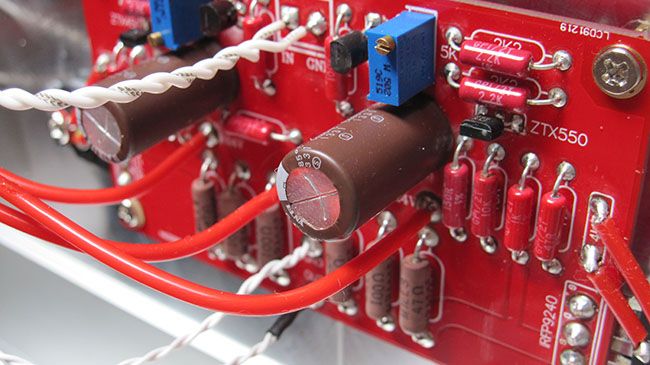
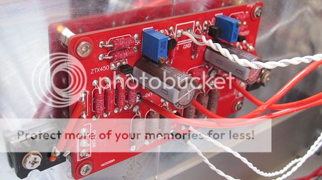
How about some photos of the full rig? Looks like some very nice workmanship on the two you posted.
Last edited:
How about some photos of the full rig? Looks like some very nice workmanship on the two you posted.
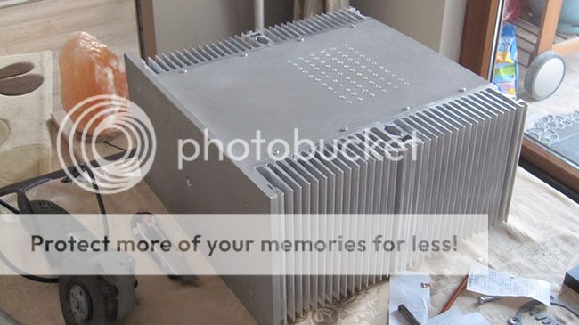
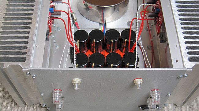
of course.
Lets start with the case home made. It is really huge
Audio grade Transformator, 400VA 18-0-18 centertap comes from Toroidy. Caps are Mundorf Mlytic AG 35v 22.000uf
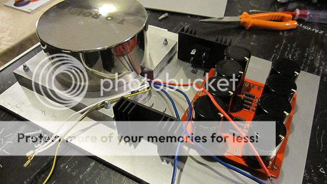
power cables are Neotech 7N Copper 16g, Mundorf pure silver for speakers binding and Black Rhodium Illusion dct+ for RCA..
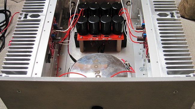
and silver plated CMC connectors, Oyaide Inlet-R
- Home
- Amplifiers
- Pass Labs
- F5 power amplifier