woody said:But wouldn't the Zen-Lite be better for growing pot? Lets see
the more bias on the Zen-lite the more light, more light the better the pot will grow, the better the pot grows the better the music will sound.
............ 'till short circ between headphones .............

Zen Mod said:
............ 'till short circ between headphones .............
Settle in
 that could take a while...
7/10
The crosstalk I got was so low that I couldn't measure it
That's good to know. Those Plitrons are $90 a pop.
Nice to keep costs down these days.
...I know, I know. Even if I needed 2, it would be worth it.
Thanks!
V~
vdi_nenna said:Those Plitrons are $90 a pop.
I guess I made a nice investment.
bogdan_borko said:
damn that's beautiful. I can't tell if the caps are optional? Am I seeing that correct? It both looks like they are, and they aren't.
-Jared
defect9 said:
damn that's beautiful. I can't tell if the caps are optional? Am I seeing that correct? It both looks like they are, and they aren't.
-Jared
C3 and C4 are 470uF power supply caps ( bypassed with 100nF C1 and C2) and of course they`re optional...
Assesears said:
G'Day,
For sale?.
It depends of how many of you are interested and what`s mr.Pass thinks of that idea, it`s his design after all.
Well, posting this after Borkos superb PCBs  will make me ridiculous at the face of the whole DIY community...
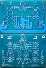
As an exercice, I tried to copy - shame on me - Admirable Nelson's FW PCB and I am not very satisfied with the result.
Especially the connection between Q5 and input Jfet seems less than convincing on my layout, but my weeny brain cannot find a better way.
Any Idea ...?
Or should I best give up?
Manu
will make me ridiculous at the face of the whole DIY community... As an exercice, I tried to copy - shame on me - Admirable Nelson's FW PCB and I am not very satisfied with the result.
Especially the connection between Q5 and input Jfet seems less than convincing on my layout, but my weeny brain cannot find a better way.
Any Idea ...?
Or should I best give up?
Manu
Attachments
bogdan_borko said:
It depends of how many of you are interested and what`s mr.Pass thinks of that idea, it`s his design after all.
Perhaps we should send someone to Serbia to snatch Jelina ..to be held for ransom...specifically availability of those beautiful PCBs.
NICE JOB!! Such talent!!(and sooo young).
" and what's mr. Pass thinks of that idea".....
Manu said:Well, posting this after Borkos superb PCBs
As an exercice, I tried to copy - shame on me - Admirable Nelson's FW PCB and I am not very satisfied with the result.
Especially the connection between Q5 and input Jfet seems less than convincing on my layout, but my weeny brain cannot find a better way.
Any Idea ...?
Or should I best give up?
Manu
I like them
YGFM
jacco vermeulen said:
comme ci, comme ça
jacco vermeulen said:
Jacco that was very cruel of you

Few days ago I`ve seen one of mine beginner`s post and I`ve blushed
My english is a bit better now, I hope but more important I made a good progress in audio electronics, made my Aleph variation "Krypton": http://www.diyaudio.com/forums/showthread.php?s=&threadid=109097&highlight=
and I`m now deep in developing my low feedback class a hybrid amplifier and I`m happy abou it
Cheers!
Borko.
> but if I need more power , how do I do ?
If you consider the dissipation on each MOSFET, they are at 24V 1.3A bias -> about 30W. I would not advise you to go beyond that. So more power always means more MOSFETs.
The maximum output is designed at about 20V 2.6A, i.e. optimised for 8ohm load.
If you have a high impedance speaker, you need more drive voltage. Probably easiest is to drive 2x F5 as bridged amps feeding one speaker using balanced input. Maximum power is now optimised for 16 ohm load.
If you have a low impedance speaker, you need more current rather than voltage. You can of course start paralleling matched output devices (e.g. using 2 pairs of MOSFETs will give maximum power at 4 ohm). But paralleling MOSFETs will change the frequency dependent characteristics of the amplifier.
Patrick
- Home
- Amplifiers
- Pass Labs
- F5 power amplifier