Re: Another view
Oh no! You've added caps.")
Seriously, I wonder what difference in performance one
might expect if IRF610/9610s were used instead of
those cute little jfets.
Dennis
P.S. Love you avatar, Darth Jam
jam said:Not to take anything away from Mr.Pass's excellent design .......bipolar outputs and not nearly as elegant as the A5..........but the use of cascodes might help if higher power levels are required.
Jam
Oh no! You've added caps.
Seriously, I wonder what difference in performance one
might expect if IRF610/9610s were used instead of
those cute little jfets.
Dennis
P.S. Love you avatar, Darth Jam
Re: Another view
naah .....
elegance in feedback is missing ............
jam said:Not to take anything away from Mr.Pass's excellent design .......bipolar outputs and not nearly as elegant as the A5..........but the use of cascodes might help if higher power levels are required.
Jam
naah .....
elegance in feedback is missing ............
Re: Re: Another view
I would suspect you'd get similar differences that you see between the Aleph 30 and the Aleph J.
Only 1 'real' way to find out eh Dennis

Dennis Hui said:
Oh no! You've added caps.
Seriously, I wonder what difference in performance one
might expect if IRF610/9610s were used instead of
those cute little jfets.
Dennis
P.S. Love you avatar, Darth Jam
I would suspect you'd get similar differences that you see between the Aleph 30 and the Aleph J.
Only 1 'real' way to find out eh Dennis
Nelson Pass said:
Current through one hundred
Pinched the front end bias is
Output Source matters not
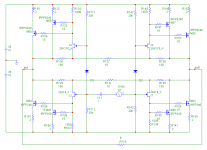
Thank you for your help Nelson.
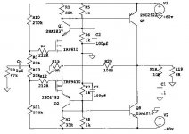
I have looked at my circuit for a while and I guess the reason for my confusion is, because I didn't have an IRFP240/9240 in my library of components, I used an IFR540/9540 instead which initially looks like it has similar specs but of course it doesn't.
I eventually imported a IRFP240 into my schematic and changed the biasing to match.
I hope this new version is better.
Cheers
Tim
Attachments
 Spectrally, they looked great
 Ok so you hate caps.............we could replace the mosfets with jfets and the outputs with Mosfets and if we ran 55volt rails we could have a hundred watt amp.
My main concern then would be maintaining bias stability.......maybe Mr.Pass would care to comment........
So you like the Avatar Dennis(I hope I don't get into trouble for this)..................may the force be with you. ...........and Grey beware.....
Regards,
Jam
My main concern then would be maintaining bias stability.......maybe Mr.Pass would care to comment........
So you like the Avatar Dennis(I hope I don't get into trouble for this)..................may the force be with you.
...........and Grey beware..... Regards,
Jam
Attachments

jam said:Ok so you hate caps.............we could replace the mosfets with jfets and the outputs with Mosfets and if we ran 55volt rails we could have a hundred watt amp.
My main concern then would be maintaining bias stability.......maybe Mr.Pass would care to comment........
Sometimes you need to use caps. You just get a little smile when
you don't have to, one benefit being that you avoid cap fetishism.
jam said:... hundred watt amp.
A Yo ... Bu Xing ...
I am trying to cook "F" ...
Tasteful "F" watts ...

F5 Pcb
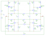
Here is one way we could lay a one sided board for the F5 circuit based directly on Nelson’s schematic.
Still on the proofing stage so suggestions, discussion and corrections are welcomed.
Needing components to attach the blue LED that will be added soon so no nasty for this omission please.
Nelson, thanks for sharing this wonderful amp that I’m sure will transcend time and be regarded as a classic.
Here is one way we could lay a one sided board for the F5 circuit based directly on Nelson’s schematic.
Still on the proofing stage so suggestions, discussion and corrections are welcomed.
Needing components to attach the blue LED that will be added soon so no nasty
for this omission please.Nelson, thanks for sharing this wonderful amp that I’m sure will transcend time and be regarded as a classic.
Attachments
Re: F5 Pcb
let jfets
each other hugs
free in the wind

apassgear said:Here is one way we could lay a one sided board for the F5 circuit based directly on Nelson’s schematic.
Still on the proofing stage so suggestions, discussion and corrections are welcomed.
Needing components to attach the blue LED that will be added soon so no nasty
Nelson, thanks for sharing this wonderful amp that I’m sure will transcend time and be regarded as a classic.
let jfets
each other hugs
free in the wind
Zayan said:... will run so hot, can you increase the distance of them to around 6 inches.
Yeah...
I often wonder why many of diyers here are not using the chassis space (or wide heat sink area) efficiently for better heat distribution. In general, they are eager to make the signal path as short as possible, and crowded layout with the components... But, at the cost of probable short FET-life, for what...? Better sound? Beauty? Anyone can explain?
Babowana said:
Yeah...
I often wonder why many of diyers here are not using the chassis space (or wide heat sink area) efficiently for better heat distribution. In general, they are eager to make the signal path as short as possible, and crowded layout with the components... But, at the cost of probable short FET-life, for what...? Better sound? Beauty? Anyone can explain?
Could it be driven by the standard sizes economically available from the manufacturers of short run pcb's?
Compare the F4 board from PD with original layout per NP for instance.
TimS said:How about scaling the balanced design for more power.
Please remember that the JFETs you are considering to use
have maximum Vgds of 25V...
- Home
- Amplifiers
- Pass Labs
- F5 power amplifier