Zen Mod said:
why you didn't asked ?
either increase current through input LTP , or increase values of theirs drain resistors ........... or slightly decrease source resistors of outputs .....that last is maybe best solution
It's in the tube for future playing around. As for now I'm waiting for the boards.
I though did some playing around with my previous prototype, and 200mA seems to be the point of diminishing returns.
I can't be bothered to make a birds nest, when I know that boards are coming soon.....and besides that I have other things to play with ATM

Magura
hershann said:For the Pumpkin - assuming the max output cap of 10uF - I guess it will still not be adequate for a headphone with input impedance of 300ohm as the LP filter will still be loping off a huge chunk of the bass.
Thinking of using the balanced output to do double duty to drive a balanced headphone too. I guess the only for this is to add an electrolytic
her shann
you can find decent electrolytics in range 100-220 uF, and you can bypass them with something nice , in range of 1-2u2 ;
just hang them ( electrolytics)on inner side of present output caps , solder 47K from output side of caps to gnd ( for bleeding those big caps ) , connect da cans and enjoy .
as I said - I tried my proto Pumpie with AKG K270 Studio ........
nota bene - do not forget to power off power amp, when you are in mood for headphones ........

naaaaaaaah......
I'm ill like a dog ........ flue almost gets me completely ..........
Maître Zen,
With AKG 270 corner freq will be about 20Hz with 100uF cap. Is it still oK,
or is it best to go 220uF in any case?
Wish you speedy gonzales recovery...
With AKG 270 corner freq will be about 20Hz with 100uF cap. Is it still oK,
or is it best to go 220uF in any case?
I'm ill like a dog ........ flue almost gets me completely ..........
Wish you speedy gonzales recovery...
Zen Mod said:
you can find decent electrolytics in range 100-220 uF, and you can bypass them with something nice , in range of 1-2u2 ;
just hang them ( electrolytics)on inner side of present output caps , solder 47K from output side of caps to gnd ( for bleeding those big caps ) , connect da cans and enjoy .
as I said - I tried my proto Pumpie with AKG K270 Studio ........
nota bene - do not forget to power off power amp, when you are in mood for headphones ........
naaaaaaaah......
I'm ill like a dog ........ flue almost gets me completely ..........
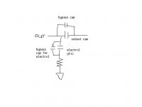
Pardon my poor comprehension - so you mean -ve leg of electrolytic to output of film cap and +ve leg of electrolytic to resistor which is then connected to ground. So the electrolytic is not actually parallel to the film cap at all.
Attachments
hershann said:
Pardon my poor comprehension - so you mean -ve leg of electrolytic to output of film cap and +ve leg of electrolytic to resistor which is then connected to ground. So the electrolytic is not actually parallel to the film cap at all.
Your drawing is not excactly correct! The Electrolytic cap must be in parallel with the outputcap. Said in another way; you can replace the outputcap, with the electrolytic (and add the resistor as Mr. ZM said)
Edit: And bypass the electrolytic with your faverourite filmcap ofcourse
I beleive there is provided for that on the Shunty boards...Edit Edit: I would use at least 220uF, and even that, I feel is too small. I usally go for 1000uF for headphone applications like that.
One good combo that I can recommend is 470uF Panasonic FC bypassed with a 1uF Rifa PHE426 polyprop. At least that is the best sounding "cheapo" combo that I have ever heard
Using a smallish cap on the output of a Headphone amp does cut the lower octaves somewhatBiggest Burleska
Yup I was trying to be clever. I know that inductance isn't important for DC so my point is that an inductive resistor is actually better in the power supply as it might (theoretically ) filter out a teeny bit noise and ripple. So part of point was that those who would blindly replace resistors with a "better" non-inductive one might be wrong...
I will never try to be "clever " again...promise...
Variac said:
Yup I was trying to be clever. I know that inductance isn't important for DC so my point is that an inductive resistor is actually better in the power supply as it might (theoretically ) filter out a teeny bit noise and ripple. So part of point was that those who would blindly replace resistors with a "better" non-inductive one might be wrong...
I will never try to be "clever " again...promise...
Naah, dont think so. First you were right, then you were right again!!!!
Use the most inductive resistor that you can find for CRC arrangements"!!!"You better play "clever" some more
hershann said:
Pardon my poor comprehension - so you mean -ve leg of electrolytic to output of film cap and +ve leg of electrolytic to resistor which is then connected to ground. So the electrolytic is not actually parallel to the film cap at all.
steenoe said:
Your drawing is not excactly correct! The Electrolytic cap must be in parallel with the outputcap. Said in another way; you can replace the outputcap, with the electrolytic (and add the resistor as Mr. ZM said)
Edit: And bypass the electrolytic with your faverourite filmcap ofcourse
Edit Edit: I would use at least 220uF, and even that, I feel is too small. I usally go for 1000uF for headphone applications like that.
One good combo that I can recommend is 470uF Panasonic FC bypassed with a 1uF Rifa PHE426 polyprop. At least that is the best sounding "cheapo" combo that I have ever heard
In that case - it's just replacing the output cap or paralleling the output cap with an electrolytic then. Since there is already a R27/R29 (100k) shunting to ground, why is there a mention of having a 47k ohm resistor connected to ground? Is that to replace R27/R29?
Will the electrolytic cap degrade the sound somewhat when the pumpkin is used as a preamp then?
her shann
hershann said:
Pardon my poor comprehension - so you mean -ve leg of electrolytic to output of film cap and +ve leg of electrolytic to resistor which is then connected to ground. So the electrolytic is not actually parallel to the film cap at all.
Attachments
I know there has been many discussions about output capacitors. I am thinking of using these:
http://cgi.ebay.com/Obbligato-Premi...eZWD1VQQtrksidZp1638.m118.l1247QQcmdZViewItem
Just wondering if off board mounting (as these are too big) are a bad idea for output caps? - I know off board mounting can be bad for power supply caps due to the long leads.
Or should I just stick to something that can fit the footprint - like the Wima MKP4, Epcos film cap, Mundorf (cheap series) . The really expensive boutique caps can clean out my wallet really fast. (need 4 with Pumpkin!
her shann
http://cgi.ebay.com/Obbligato-Premi...eZWD1VQQtrksidZp1638.m118.l1247QQcmdZViewItem
Just wondering if off board mounting (as these are too big) are a bad idea for output caps? - I know off board mounting can be bad for power supply caps due to the long leads.
Or should I just stick to something that can fit the footprint - like the Wima MKP4, Epcos film cap, Mundorf (cheap series)
. The really expensive boutique caps can clean out my wallet really fast. (need 4 with Pumpkin!her shann
hershann said:..........
Or should I just stick to something that can fit the footprint - like the Wima MKP4, Epcos film cap, Mundorf (cheap series)
her shann
yes.
AuroraB said:Oh, Man!......I've bee trying to read through this thread, but this combination of Elephant beer and Slivovic just makes my head spin....
Since I'm in a situation of just being able to continue to gather information for yet another year ( hopefully less), I just wonder if the PCBs for Pump&Shunty were public... can't seem to find them?
nope
I think that these few treads , schematics and Cook Book are enough .........

but I'll not make any fuss if someone publish his own variant .........

Thinking of putting together the Opus balanced DAC (as described in the Digital section of the forum) to feed the pumpkin.
Can the Pumpkin accept a common mode DC of 2.5V? I am wondering if I can omit the DC coupling caps at the DAC output to improve its sound.
The pumpkin has output caps - thus will block any DC from going to the power amp - but will the DC itself damage the preamp?
her shann
Can the Pumpkin accept a common mode DC of 2.5V? I am wondering if I can omit the DC coupling caps at the DAC output to improve its sound.
The pumpkin has output caps - thus will block any DC from going to the power amp - but will the DC itself damage the preamp?
her shann
hershann said:Thinking of putting together the Opus balanced DAC (as described in the Digital section of the forum) to feed the pumpkin.
Can the Pumpkin accept a common mode DC of 2.5V? I am wondering if I can omit the DC coupling caps at the DAC output to improve its sound.
The pumpkin has output caps - thus will block any DC from going to the power amp - but will the DC itself damage the preamp?
her shann
nope ; you can't do that - from two reasons - you have attenuator ( pot ) on input which is based on ground ; even in case that you use shunt attenuator (between two inputs , without connection to gnd) , gates are still leaned/based on gnd
after universal Headphone preamp , you now need voltage convertor .......
you can't have anything .
put xformer on output of your DAC
Zen Mod said:
nope ; you can't do that - from two reasons - you have attenuator ( pot ) on input which is based on ground ; even in case that you use shunt attenuator (between two inputs , without connection to gnd) , gates are still leaned/based on gnd
after universal Headphone preamp , you now need voltage convertor .......
you can't have anything .
put xformer on output of your DAC
We are GREEDY boys - 1 Pumpkin to rule (do) them all!
I'll just use the coupling caps on the output of the DAC then before feeding the Pumpkin.
her shann
Cookbook says EI transformer is preferred - I supposed due to better noise characteristics and ability to withstand DC etc.
For my Pumpkin the transformer is going to be mounted near the front panel and the audio circuit right at the back (the pot probably actuated via an extension rod).
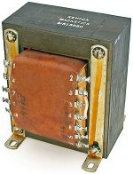
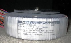
So should I go for the old EI transformer 250VA, 42VCT x2 (pic 1) or the toroidal transformer 600VA 90VCT (pic 2). They are similar in price - with the EI at $20 and toroidal at $29.5.
BTW how easy is it to shield the EI's stray magnetic field?
her shann
For my Pumpkin the transformer is going to be mounted near the front panel and the audio circuit right at the back (the pot probably actuated via an extension rod).
So should I go for the old EI transformer 250VA, 42VCT x2 (pic 1) or the toroidal transformer 600VA 90VCT (pic 2). They are similar in price - with the EI at $20 and toroidal at $29.5.
BTW how easy is it to shield the EI's stray magnetic field?
her shann
Attachments
hershann said:Cookbook says EI transformer is preferred - I supposed due to better noise characteristics and ability to withstand DC etc.
For my Pumpkin the transformer is going to be mounted near the front panel and the audio circuit right at the back (the pot probably actuated via an extension rod).
So should I go for the old EI transformer 250VA, 42VCT x2 (pic 1) or the toroidal transformer 600VA 90VCT (pic 2). They are similar in price - with the EI at $20 and toroidal at $29.5.
BTW how easy is it to shield the EI's stray magnetic field?
her shann
use that EI and place it in separate box ; 600VA donut is really overkill ....... even for Pumpkin
both transformers you show are probably too large ( physically and inducing hum wise) to be in same box with active electronic
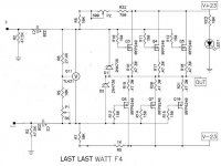
last last watt F4
you can probably drive it balanced ........ with omitting few last resistors in Pumpie , you can also omit input resistors and big input caps on this last last watt F4 .......
or I'm missing something ....... as usual .........
you can probably drive it balanced ........ with omitting few last resistors in Pumpie , you can also omit input resistors and big input caps on this last last watt F4 .......
or I'm missing something ....... as usual .........
Attachments
- Status
- Not open for further replies.
- Home
- Amplifiers
- Pass Labs
- Pumpkin preamp - More Boring Making Thread