I need some help in regard to the IRFP9610 heat sink. If you look at the pic below, heatsinks for the IRFP9610 are touching (Labelled 37 and 6). My question is there is a continuity between the two heatsinks with both "cooling tab"s (where you put the screw in), is it ok or it is a big no? Also, is it possible making a 10pf condensator with just a capacitance meter? THank you for your help in advance.
Attachments
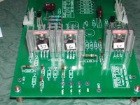
You can always isolate the IRF9610 from the heatsink using the proper insulators (including the bushing for the screw!). This way, it doesn't matter if the heatsinks touch each other. I don't remember the circuit diagram, but if the center tabs of both MOSFETs are at the same potential (ie connected to the same point in the schematic), then you can leave out the insulation altogether which makes for a better heat transfer.
Re: Hi, Dale
It seems to me the only thing you should have insulated (9610), you haven't. The rest is pretty much useless.
Heat here is of no consequence, all you are doing is making it incredibly long to put the board together (which may prolong your enjoyment") ), lenghtening the signal path, and making it impossible to probe voltages during testing.
), lenghtening the signal path, and making it impossible to probe voltages during testing.
TjongKristian said:They are clear heatshrink which fit most of the component's "leg." The reason I raise the component because I thought it looks neat and better performancedue to the heat dissipation.
It seems to me the only thing you should have insulated (9610), you haven't. The rest is pretty much useless.
Heat here is of no consequence, all you are doing is making it incredibly long to put the board together (which may prolong your enjoyment
), lenghtening the signal path, and making it impossible to probe voltages during testing.Hi Paolo (grataku),
I was thinking the exact same thing, but was afraid to write that down. I needed to check my voltages during testing. Would have been very difficult with heat tubing.
I have heard of raising some components off the board slightly to add a small space for air to flow. Slightly means barely visible...
Kristian, we are not trying to "dis" you, just trying to understand and help others.
Best Regards,
Dale
Thank you for the info.
Bawang,
Thanks for the info, I will check the schematic for that.
Grataku,
Yes, Grataku, Indeed the heatshrink prolong my enjoyment . I try to anticipate the voltage measurement by either turning the board upside down or using the tip of my DMM's probe (the board is thruhole), it is quite cumbersome, but most important of all, I am enjoy looking at the neat board.
Dale,
I also would like to express my deepest gratitude to Brian and Dale for their effort which allows me (and others) to get a chance to hear one of the best amp that otherwise will be unaffordable (for me at least).
The only thing that I am afraid when the Aleph 2 is done that suddenly my preamp is not good enough, and then I realized my speaker is not giving me enough. The whole world starting to crumble in front of my eyes..........
Bawang,
Thanks for the info, I will check the schematic for that.
Grataku,
Yes, Grataku, Indeed the heatshrink prolong my enjoyment
. I try to anticipate the voltage measurement by either turning the board upside down or using the tip of my DMM's probe (the board is thruhole), it is quite cumbersome, but most important of all, I am enjoy looking at the neat board. Dale,
I also would like to express my deepest gratitude to Brian and Dale for their effort which allows me (and others) to get a chance to hear one of the best amp that otherwise will be unaffordable (for me at least).
The only thing that I am afraid when the Aleph 2 is done that suddenly my preamp is not good enough, and then I realized my speaker is not giving me enough. The whole world starting to crumble in front of my eyes..........
TjongKristian,
Looking at your component installation reminds me that there is one area that I would like (but forgot to mention) BrianGT/Harvadian to incorporate into the board layout for the second batch of group buys ... and that is ... to have the component call out to be shown outside of the rectangular box (i.e. not directly below the components) ... just like the Aleph-X boards. No big deal but ...
Dale/Brian,
If there is going to be a third group buys (or is it fourth?), is this something that can be done easily?
Hi Roderick,
Moving the reference designators is very easy. If not carefully done, it can lead to confusion. A trade off. The important thing is to try and be consistent (i.e. always below, or to the right, etc).
I just ordered more boards, but made no changes to them.
Dale
Moving the reference designators is very easy. If not carefully done, it can lead to confusion. A trade off. The important thing is to try and be consistent (i.e. always below, or to the right, etc).
I just ordered more boards, but made no changes to them.
Dale
Re: Caps question
I don't think Nelson cares all that much about components as long as they have decent specs, if you look at the XA200 pics he posted here it's all digikey type parts, like panasonics PP for ac coupling etc. The whole thing just naturally sounds good because the design is good. If you added black gates here and there it would probably sound sublime that's why I started the BG bulk purchase.
Asen said:What caps does Mr. Pass use in the original ALEPHs? Black Gates?
Thanks
I don't think Nelson cares all that much about components as long as they have decent specs, if you look at the XA200 pics he posted here it's all digikey type parts, like panasonics PP for ac coupling etc. The whole thing just naturally sounds good because the design is good. If you added black gates here and there it would probably sound sublime that's why I started the BG bulk purchase.
When looking at your PCB, it's hard not to notice that you are using very long leads to components and also dress them in a sort of plastic jacket. First of all, it is all extra work and actually it is something not desirable. Just trim them as short as possible (especially for TO-92 semis and mica caps) and don't be afraid to rest them on a board.
This is not production and you should pay different kind of attention to small details.
This is not production and you should pay different kind of attention to small details.
Hi Kristian,
The IRFP9610 has it's Drain connected to it's flange. The Drain is the center pin (I don't know the other type with an extra pin). The Drains of each differential pairs do not meet each other. The Sources do.
I don't know the insulator you use for the component leads, but using materials similar to cable insulators, I used to be able to locate the degradation in the sound quality. Disagree? Well, remove from one channel and compare. If you can't hear the improvement, don't sue me.
I also used to mount components off the board like yours. Sometimes even times longer. Especially for expensive capacitors and resistors. This is to allow for the components to migrate from PCB to PCB.
Hey, where do you get that Pass Labs' PCB? Damm, I don't have a credit card!
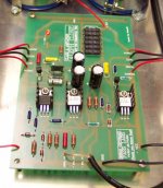
Mark A. Gulbrandsen said:The heatsinks are also not really needed but do look nice. I used different sinks on mine as the photo below shows......
The IRF on current source passes higher current than IRF in the differential pairs, and sure will get hotter (so you may want to add heatsink here). The higher the current usually the better the performance (so you won't want to add resistance to offset the DC in current source).
MOSFET can withstand a higher temperature than it will experience here, but ("they" say) will reduce the MOSFET life. The last statement may be useless. What you may want to hear is whether such temperature (I think more than 100C) will degradate the performance to an audible degree. Because the MOSFET will be damaged or replaced long before it's usefull life anyway.
Power disipated by the IRF9610s
My back of the envelope calculations are as follows:
Firstly the diff. pair's current source:
The IRF9610's source is around 6 Volts below the +Rail (assuming Vgs = 3 Volts)
Therefore with a 220 ohm resistor, current is around 27mA
The drain is 3 Volts (Vgs) above ground.
Assuming the rails are +/- 15 Volts, then Vds = 15 - 6 - 3 = 6 volts, then:
Power = 6 Volts x 27 mA = 0.16 Watts
Secondly the diff. pair:
The drain of each of the diff. pair is around 4.6 Volts above the negative rail, so they have a Vds of around 13.5 Volts, but shate the current, so:
Power = 13.5 Volts x 13.5 mA = 0.18 Watts each
All pretty much the same, all inconsequential => no heatsink necessary on any of them.
Anyone like to check my calcs - (I hope my estimates of the voltages are right!)
Nic
- Status
- This old topic is closed. If you want to reopen this topic, contact a moderator using the "Report Post" button.
- Home
- Amplifiers
- Pass Labs
- IRFP9610 Heat Sink Aleph 2 Question (and others)