There seems to be significant interest in possible ways of getting SuperSymmetric operation on a monolithic chip (see the Gainclone X thread in the Solid State forum), and there have been a lot of imaginative solutions put forward, which is really great, although I don't see any of them actually working as an X circuit.
(BTW, SuperSymmetry is a trademark of Pass Laboratories)
I think perhaps it's time to pull something out of the bag and start a new thread, catering to this interest but with a little bit different direction.
Herewith I would like to present a method of doing this with a pair of op amps (or a dual op amp if you like) of the "current feedback" variety. As you may know, current feedback op amps look like regular op amps except that the (-) input pin is low impedance. They are distinguished by exceptionally wide bandwidth and stable operation, mostly because the feedback network also functions as gain degeneration for the input stage.
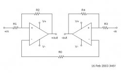
Below you (hopefully) see a diagram showing two such op amps interconnected. Each consists of a complementary pair of input followers (actually just buffers, and not conceptually significant) forming the (+) input which drive the actual complementary input devices, where the Emitters form the (-) input to the op amp. These devices in turn drive a pair of complementary output devices whose collectors form the output.
Each of these op amps is a slightly simplified version of commercially available parts. Just go to National Semiconductor's web site and look for "current feedback" op amps.
What will be unusual here is that we have joined the (-) inputs of the two op amps to form the SuperSymmetric connection between them. Each of the non-inverting (+) inputs operates at virtual ground by virtue of the feedback from the output of the opposite amplifier. This effectively makes the (+) inputs of the op amps behave as if they were (-) and vice versa.
R1 = R3, R2 = R4, and the gain is set by R2/R1. The input impedance is R1 if driven from a single-ended source, or 2*R1 from a balanced source. Any undriven inputs should be grounded.
R0 sets the open loop gain of the system, and can be adjusted upward for greater stability, or downward for more feedback. This is a good place for a potentiometer for those who like to explore these issues.
The output, of course, is balanced, and best performance is obtained by using it balanced. The input can be operated balanced or not, but gives slightly better performance when driven by a balanced source.
I haven't yet run across an example of a monolithic higher power op amp using current feedback on the market, but there is no reason that one would not exist. If you find one, it will probably make a dandy SuperSymmetric power amplifier, but until then we have to content ourselves with low power.
Or build something discretely......
Happy Valentine's Day.
(BTW, SuperSymmetry is a trademark of Pass Laboratories)
I think perhaps it's time to pull something out of the bag and start a new thread, catering to this interest but with a little bit different direction.
Herewith I would like to present a method of doing this with a pair of op amps (or a dual op amp if you like) of the "current feedback" variety. As you may know, current feedback op amps look like regular op amps except that the (-) input pin is low impedance. They are distinguished by exceptionally wide bandwidth and stable operation, mostly because the feedback network also functions as gain degeneration for the input stage.
Below you (hopefully) see a diagram showing two such op amps interconnected. Each consists of a complementary pair of input followers (actually just buffers, and not conceptually significant) forming the (+) input which drive the actual complementary input devices, where the Emitters form the (-) input to the op amp. These devices in turn drive a pair of complementary output devices whose collectors form the output.
Each of these op amps is a slightly simplified version of commercially available parts. Just go to National Semiconductor's web site and look for "current feedback" op amps.
What will be unusual here is that we have joined the (-) inputs of the two op amps to form the SuperSymmetric connection between them. Each of the non-inverting (+) inputs operates at virtual ground by virtue of the feedback from the output of the opposite amplifier. This effectively makes the (+) inputs of the op amps behave as if they were (-) and vice versa.
R1 = R3, R2 = R4, and the gain is set by R2/R1. The input impedance is R1 if driven from a single-ended source, or 2*R1 from a balanced source. Any undriven inputs should be grounded.
R0 sets the open loop gain of the system, and can be adjusted upward for greater stability, or downward for more feedback. This is a good place for a potentiometer for those who like to explore these issues.
The output, of course, is balanced, and best performance is obtained by using it balanced. The input can be operated balanced or not, but gives slightly better performance when driven by a balanced source.
I haven't yet run across an example of a monolithic higher power op amp using current feedback on the market, but there is no reason that one would not exist. If you find one, it will probably make a dandy SuperSymmetric power amplifier, but until then we have to content ourselves with low power.
Or build something discretely......
Happy Valentine's Day.
Attachments
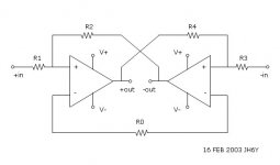
jh6you said:This way if I redraw using op-amps...?
Not quite. Your feedback resistors need to be cross connected. R2 to -OUT and R4 to +OUT.
se
Nelson Pass said:I haven't yet run across an example of a monolithic higher power op amp using current feedback on the market, but there is no reason that one would not exist. If you find one, it will probably make a dandy SuperSymmetric power amplifier, but until then we have to content ourselves with low power.
Or build something discretely......
Well, if you want EVERYTHING in a single package. Otherwise, you could just tack on a pair of simple, single-ended followers.
By the way, it might also be worth mentioning that current mode opamps are also referred to as Norton amplifiers.
se
Attachments
jh6you said:It was a mistake. Here it is.
There ya go. And if you want to really get technical, you can draw the opamps with current source symbols between the inputs (to indicate a current mode amplifier as opposed to a voltage mode amplifier) and make the power supply single-ended.
")
se
Actually, these aren't current mode inputs as such,
that is to say they aren't Nortons. (Frankly I hadn't
considered whether Nortons would do the job or not:
I imagine they could)
I was referring to "current feedback" op amps, whose (+)
input is high impedance. It's the (-) that's low.
As such, they do not require a single ended supply.
that is to say they aren't Nortons. (Frankly I hadn't
considered whether Nortons would do the job or not:
I imagine they could)
I was referring to "current feedback" op amps, whose (+)
input is high impedance. It's the (-) that's low.
As such, they do not require a single ended supply.
Steve Eddy said:
really get technical
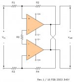
I have just thought about only the concept what Nelson Pass explains. Accordingly, the drawing is a conceptual sketch. Is the following new conceptual sketch better? As a professional technician, could you kindly recommend the resistor values for the practical approach? Thanks.
JH
Attachments
Nelson Pass said:Actually, these aren't current mode inputs as such,
that is to say they aren't Nortons. (Frankly I hadn't
considered whether Nortons would do the job or not:
I imagine they could)
I was referring to "current feedback" op amps, whose (+)
input is high impedance. It's the (-) that's low.
As such, they do not require a single ended supply.
Right. Sorry. I'd been following some of the X-Gainclone thread and had been mulling over doing it with Nortons. When I saw your post regarding pulling it off with opamps, I was still thinking of Nortons.
se
jh6you said:I have just thought about only the concept what Nelson Pass explains. Accordingly, the drawing is a conceptual sketch. Is the following new conceptual sketch better? As a professional technician, could you kindly recommend the resistor values for the practical approach? Thanks.
It's certainly a much more elegant drawing.
As for resistor values, the ideal feedback resistor (R2 and R4 in your drawing) value is rather device dependent and should be determined by the information given in the datasheet of the particular device in question. There's a whole interrelationship between feedback resistor, power supply voltage, load impedance, and closed loop gain that make designing with these kinds of opamps a bit more complicated than your basic voltage feedback opamp.
So I guess the first order of business would be to pick a readily available device to start with.
se
Bridging amplifiers
I suspect the circuit configurations being discussed using two Op amps or two power amplifiers with differential inputs and complementary driven pairs in the output stages will very likely provide better performance than the X project. My reasoning for this is that a current source in the output stage of the X provides a non symmetrical output and that thus AC feedback has to be applied to the current source in a effort the reduce, but not eliminate this problem completely. In a amplifier configured in a X configuration in which both the upper half and the negative halves of the output stage are actively driven directly by the amplified input signal much of the unsymmetrical nature of the output signal is automatically eliminated. This also allows sourcing of equal currents for positive and negative going signals and that thus the output will be more linear and have improved efficiency. This will be most noticeable when driven harder.
I suspect that there are quite a good number of amplifiers already on the market that use the same or near the same circuit configuration as is being discussed. I suspect this since bridged amplifiers have been around well prior to 1965 as I recall.
The cross-coupled feed back from one side to the other is typical balanced audio line drivers. Nothing new there.
John Fassotte
Alaskan Audio
This could probably be a future diy project....... perhaps?
Please the active crossover first!
Re: Bridging amplifiers
In point of fact there is something new here, and you seem
to have missed the essence of it.
alaskanaudio said:The cross-coupled feed back from one side to the other is typical balanced audio line drivers. Nothing new there.
In point of fact there is something new here, and you seem
to have missed the essence of it.

- Status
- This old topic is closed. If you want to reopen this topic, contact a moderator using the "Report Post" button.
- Home
- Amplifiers
- Pass Labs
- Monolithic SuperSymmetry with Current Feedback