Sad but true, I’m still working on my first electronic project ever which I started in 2002. Okay, I know that my pre is working but I still haven’t got a chance to finish it, and I don’t know if I ever will. At least with the tempo I have and with all opportunities there is today with LCD screens and every thing. Tough I have now decided to at least get my pre in to a home made chassi, which is more or less finished.
I could have started with an easier project, but what doesn’t kill you will make you stronger. And believe it or not I have my volume control with a PIC up and running.
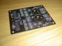
Five years ago I started to draw in the PCB layout and I also got it up und running. But today when I look at my old PCB’s they doesn’t look that nice I have to admit, and they are too big to get in to the chassi I’ve built (normal size). So now I am working on a new layout and I have to admit that I have been looking quite a lot on the design that veteran made a group buy on. But this one is double sided and I will be using Black Gate N capacitors for my pre.
I would really appreciate if you could give me some comments on the layout. I have not made the fine tuning of the traces yet so pls see it as a draft.
When I have finished the layout I will be happy to share it with all you guys how have made my project possible, especially Nelson him self.
Thanks in advance
/loovet
I could have started with an easier project, but what doesn’t kill you will make you stronger. And believe it or not I have my volume control with a PIC up and running.
Five years ago I started to draw in the PCB layout and I also got it up und running. But today when I look at my old PCB’s they doesn’t look that nice I have to admit, and they are too big to get in to the chassi I’ve built (normal size). So now I am working on a new layout and I have to admit that I have been looking quite a lot on the design that veteran made a group buy on. But this one is double sided and I will be using Black Gate N capacitors for my pre.
I would really appreciate if you could give me some comments on the layout. I have not made the fine tuning of the traces yet so pls see it as a draft.
When I have finished the layout I will be happy to share it with all you guys how have made my project possible, especially Nelson him self.
Thanks in advance
/loovet
Attachments
Hi loovet!
I'm myself pretty new to pcb-layout, so please take my advice with a grain of salt.
While the parts are layouted symmetrically, the traces aren't. This won't mean the layout won't work, but it's not elegant. If you're ambitious to draw optimum traces, I would say there's in a symmetrical design only one way, not two; thus a symmetrical schematic should yield also a symmetrical layout.
Further I will need a far wider ground trace which will be problematic due to pad spacings. There's enough space to move the parts a bit apart.
Next I see some traces crossing the pads of the big caps which does not seem to be your intention, so this would give a connection problem? Further you fork a trace in the middle of the left big cap which is also not optimal since it's not the shortest path possible (the forked trace runs in parallel for quite some time).
At C9 I see a trace that seems to go nowhere?
I'm sure you will get a nice layout!
All the best and have fun! Hannes
h_a thanks for the input.
I've done som changes to the layout;
- I've tried to make it as symmetrical as possible
- I've made a wider ground trace
- I've made a Star ground (at least as much as possible)
Pls feel free to add your comments.
BR
/loovet
BTW one of the pads on the left capacitor is a dummy, and want affect the circuit
Attachments

Nice!
have you tried it out yet?
what kind of volume control are you going to use?
Output vol or input?
Have you checked the noise on the tweeter?
This design is inclined to give you a little hiss on the tweeter, but if you properly ground it and distribute the gain of the stage and the output potentiometer's value you can get it pretty much dead silent.
keep us update.
Best.
Stefano.
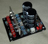
Hi Sefanno,
I've tried it out and it works. But so far I've only been able to try it out with an Ipod and my headphones, but never the less it works.
I will use this volume control and it will be on the output...
http://www.diyaudio.com/forums/showthread.php?s=&threadid=102272
Attached a picture of the stuffed board ;-)
BR
/loovet
Attachments
- Status
- This old topic is closed. If you want to reopen this topic, contact a moderator using the "Report Post" button.
- Home
- Amplifiers
- Pass Labs
- PCB help Aleph P