(With apologies to Oscar Wilde...)
There's always a lot of talk about output stage bias, but you
don't see too many graphic examples designed to illustrate the
value of bias current in lowering distortion.
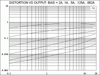
Here's a curve of a complementary Mosfet follower operated
without feedback into 8 ohms and biased at a number of
idling current values from 62 mA to 2A. (The lowest curve is
2 amps).
Notice the heavy dependence of distortion on the bias current.
Notice also that there is roughly an inverse proportion between
bias and distortion.
We are running curves from Class AB through twice the Class A
value for the 20 watts.
0.062A corresponds to leaving Class A at 0.125 watts peak,
0.125A = .5W, 0.25A = 2W, 0.5A = 8W, 1A = 32W, 2A = 64W
I get a lot of people who worry about the exact point where an
amp leaves Class A, as if some sort of switch gets thrown and
the amp which was delicious at 5 watts is now disgusting at
6 watts.
As you can see, there is no such abrupt change as you move from
Class A to AB mode, and we see that higher bias improves the
linearity at all power levels, not just in the Class A region.
bon apetite
There's always a lot of talk about output stage bias, but you
don't see too many graphic examples designed to illustrate the
value of bias current in lowering distortion.
Here's a curve of a complementary Mosfet follower operated
without feedback into 8 ohms and biased at a number of
idling current values from 62 mA to 2A. (The lowest curve is
2 amps).
Notice the heavy dependence of distortion on the bias current.
Notice also that there is roughly an inverse proportion between
bias and distortion.
We are running curves from Class AB through twice the Class A
value for the 20 watts.
0.062A corresponds to leaving Class A at 0.125 watts peak,
0.125A = .5W, 0.25A = 2W, 0.5A = 8W, 1A = 32W, 2A = 64W
I get a lot of people who worry about the exact point where an
amp leaves Class A, as if some sort of switch gets thrown and
the amp which was delicious at 5 watts is now disgusting at
6 watts.
As you can see, there is no such abrupt change as you move from
Class A to AB mode, and we see that higher bias improves the
linearity at all power levels, not just in the Class A region.
bon apetite
Attachments
Nelson,
Thank you for this set of examples. They do indeed graphically illustrate the point.
There has been considerable discussion recently about the relative merits of SE bias vs PP bias and the optimal ratio between the two if both are used simultaneously. I for one would appreciate some illumination on this.
One does wonder how one class A biasing electron can sound different from another. Perhaps I should ask, with apologies to George Orwell, if all electrons are equal how can some be more equal than others?
Thank you,
Graeme
jacco vermeulen said:What a gay curves, Oscar would agree.
ya think that Papa is off topic?

not in sexual meaning,except if you imply that he is transsexual, just because of lack of avatar ..........

Hi there!
It's getting hot these days...bias is increasing....I need a cold drink...
Sorry for OT, but I am getting married on Sunday, July 1st, and may be offline for a few days...
I'll hopefully be back on July 16th...
Have a nice time!
(maybe I'll peek at this forum once or twice, but that's risky )
Regards,
Vix
It's getting hot these days...bias is increasing....I need a cold drink...
Sorry for OT, but I am getting married on Sunday, July 1st, and may be offline for a few days...
I'll hopefully be back on July 16th...
Have a nice time!
(maybe I'll peek at this forum once or twice, but that's risky
)Regards,
Vix
Vix said:................
(maybe I'll peek at this forum once or twice, but that's risky
.............


Nelson,
Thankyou for the illustration.
What I find interesting is that increasing the bias in a pure SE design (no active CCS) the effect is quite audible as though there is a zone or optimum point (ref JHL 15 watt).
Of course this may vary depending on the devices and topology.
macka
Thankyou for the illustration.
What I find interesting is that increasing the bias in a pure SE design (no active CCS) the effect is quite audible as though there is a zone or optimum point (ref JHL 15 watt).
Of course this may vary depending on the devices and topology.
macka
gl said:
There has been considerable discussion recently about the relative merits of SE bias vs PP bias and the optimal ratio between the two if both are used simultaneously. I for one would appreciate some illumination on this.
One does wonder how one class A biasing electron can sound different from another. Perhaps I should ask, with apologies to George Orwell, if all electrons are equal how can some be more equal than others?
Thank you,
Graeme
Well, there's equal...and then there's equal...
No one electron can tell you much about the circuitry it has passed through. It takes a continual flow of them so that you incorporate the element of time, rather than attempt to draw conclusions from a single, discrete event. Once you have time, you can have cycles. Once you have cycles, you can begin to see patterns of deviation.
Regarding single-ended vs. push-pull: Although you would notice a decrease in overall distortion with increased bias, that particular story would be more appropriately told by a graph showing the relative levels of second harmonic to other harmonics.
And I would like to add my thanks to Nelson for initiating such an earnest discussion.
Grey
gl said:There has been considerable discussion recently about the relative merits of SE bias vs PP bias and the optimal ratio between the two if both are used simultaneously. I for one would appreciate some illumination on this.
This is a subjective call. Our five in-house listeners prefer the
sound at modest power levels when there is at least some
single-ended bias. However unless you're planning on full-power
single-ended Class A, you also need to have a substantial
push-pull bias to give a clean transition, otherwise the distortion
waveform suffers a glitch, and this is reflected in the sound.
The ratio of the two is pretty arbitrary, but I like to see single-
ended for at least the first watt or so.
GRollins said:I vote for full-Gonzo class A. We have to keep the heat sink manufacturers in business.
Grey
Yeah, and how would you keep the pizza warm otherwise?
Magura
Nelson Pass said:or so.
To keep in line with the bowler hat author celebrity of the opening post : How voguely vague.
Attachments


Nelson Pass said:(With apologies to Oscar Wilde...)
There's always a lot of talk about output stage bias, but you
don't see too many graphic examples designed to illustrate the
value of bias current in lowering distortion.
To give credit where credit is due, and just to make sure Nelson
knows that we pay attention, I think this topic is mentioned in the
Zen variation part 5 (the complemtary Zen) paper. Or have I
misunderstood (yet again)?
Here's a curve of a complementary Mosfet follower operated
without feedback into 8 ohms and biased at a number of
idling current values from 62 mA to 2A. (The lowest curve is
2 amps).
<snip>
We are running curves from Class AB through twice the Class A
value for the 20 watts.
0.062A corresponds to leaving Class A at 0.125 watts peak,
0.125A = .5W, 0.25A = 2W, 0.5A = 8W, 1A = 32W, 2A = 64W
Ok, just to make sure I understand, the X scale is peak watts, and
the Y scale is distortion, right?
If so, and if we leave Class A at 0.125 watts peak, then the graph
doesn't show much information about distortion while in Class A
operation, does it? Is the point that there is no discontinuity (ie:
there is a nice smooth curve) in the graph at the point where we
transition from Class A to Class AB? Or is there a more profound
meaning that I don't yet understand?
I don't want to slow the progress of this discussion. I honnestly
want to understand the material, and this whole topic is outside
of my area of education.
I get a lot of people who worry about the exact point where an
amp leaves Class A, as if some sort of switch gets thrown and
the amp which was delicious at 5 watts is now disgusting at
6 watts.
As you can see, there is no such abrupt change as you move from
Class A to AB mode, and we see that higher bias improves the
linearity at all power levels, not just in the Class A region.
bon apetite
So, if we are have left Class A (by which I mean that the transistors
are not conducting for the full 360 degrees), and we have no feedback,
where is the crossover distortion due to the lag or phase shift of the
transistor switching into conduction? (I really hope I'm using the right
jargon here, but I admit I'm struggling).
Also, aside from dealing with amplifier heat issues, if increased bias
current reduces THD, why aren't manufacturers having a "numbers
race", publishing their amp's bias current figure?
I am under the impression that we size wires by the amount of
current they carry. Ultimately, the signal has to go through a
speaker. Is there some type of practical limit for the amount of bias
current an amp should supply?
Dazed and confused (but still hanging in there with a smile),
Robert
we see that higher bias improves the
Are you saying I have too many output devices in my A-75????
JJ
- Status
- This old topic is closed. If you want to reopen this topic, contact a moderator using the "Report Post" button.
- Home
- Amplifiers
- Pass Labs
- The Importance of Being Biased