twitchie said:Hi Manuel,
I don't have 1M and 10ohm resistors
I etched it, but looking at it, I'm not that happy with it - I think the traces are too close together, although I did go as far as drilling and putting on the top layer graphics.
I started changing the layout again today.
Just wondering if anyone else has tried this one yet and if anyone has any impressions yet?
Stephen
My boards are so far populated. I hope I can make somme tests tomorrow after work and post some impressions.
")
Many thanks to you, Mr. pass.
Manuel
Vix said:since it works fine with 16v supply and is not (milli) amperage hungry, what about battery operation?
Since it only draws 5 mA, I suggest a 15V battery from Radio
Shack.
vdi_nenna said:but I held on
Vince,
a few years ago i bought a +10k package of metalfilms by the cheap, including values such as 1M.
Not that i was totally out of resistors, think the deal on Russian made resistors i couldn't resist was a couple of months before the big score.
Sooner or later, they always come to good use.
Sooner or later, they always come to good use.
Exactly! Now I'm waiting for a project where I can use that 250k Alps pot with dented rotation. Maybe I'll have to visit the tube forum for that.
Wait, did some say this thing runs off of 15v??

Nelson Pass said:
........ If we want to add to this circuit for better performance,
there are other ways to go.
How about cascoding ala Mr. Borbely ? any advantages / disadvantages using this arrangement ?
rgds,
G33/33

Attachments
Nelson Pass said:volts output.
Thanks, Papa, understood as the output at the source . . .
JFET BOZ looks like a joke. But, I couldn't laugh.
Actually, it looks like a Joker who scaring me.
Too simple . . . too simple . . .
What do you need more . . . ?

Babowana said:
Thanks, Papa, understood as the output at the source . . .
JFET BOZ looks like a joke. But, I couldn't laugh.
Actually, it looks like a Joker who scaring me.
Too simple . . . too simple . . .
What do you need more . . . ?
hehe
sound of one hand clapping........

Babowana said:
Too simple . . . too simple . . .
What do you need more . . . ?
Someting to lower output impedance?
Maxpou idea?
Not more than 600 Ohms is a nice target.
apassgear said:
Someting to lower output impedance?
Maxpou idea?
SRPP...........
hehe
that's going in direction to some already made preamp
Lineup Audio, 2SK170GR jfet-boz version 1.0
People hevent got anything else to do, than download Nelson Pass PDF.
... Well, for myself speaking: I do not do much anything else
----------------------------------------------------------------------------------
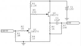
Comment to my attached SCHEMATIC
Lineup 2SK170GR Jfet BOZ - beta version 1.0a
Eventhough there are a coupe of things I would do different
and change, compared to Nelson's Qucikly posted simple circuit,
I have used same values as Nelson, in this version.
As far as I could .....
From several reasons, including:
1. Make it easy for those already having Nelson's original in mind.
2. By having similar conditions,
we can make as fair a comparison, as possible.
3. I trust Nelson Pass much. He has got experience and knows.
... you wouldnt like to change a winning setup
- not in football teams - not in amplifiers
just about the only being different in my version:
... is adding a current handling 2N5401 PNP, to 'help the jfet'
(I tried a BC640 type here fisrt, but trying like 6-7 different
the 2N5401 as 'the best'
Because this tranasistor works better at 9mA,
which is bit too high for best operation in BC560C / BC640-16.
... as 2SK170GR
is the variant I can buy up here, I use this ( IDSS max = 4.80mA, in my test circuit )
... Input Cap is optional - most cases you will NOT need it.
But just in case, you may keep it. It doesnt do no harm.
Supply Voltage is 30VDC, well regulated**.
The DC operation voltage at Ouput node is: ~10.5 VDC.
** I recommend the use of one
cheap & good TL431 adjustable zenerdiode ( 2.5V - 36V max)
plus a simple follower NPN Transisitor.
One that can deliver 10mA = total supply current
Regards
Lineup Audio Labs, the design division
/lineup
Nelson Pass said:Maybe you would like to try this first.
Attachment: jfet boz small.pdf
This has been
downloaded 338 time(s).
People hevent got anything else to do, than download Nelson Pass PDF.... Well, for myself speaking: I do not do much anything else
----------------------------------------------------------------------------------
Comment to my attached SCHEMATIC
Lineup 2SK170GR Jfet BOZ - beta version 1.0a
Eventhough there are a coupe of things I would do different
and change, compared to Nelson's Qucikly posted simple circuit,
I have used same values as Nelson, in this version.
As far as I could .....
From several reasons, including:
1. Make it easy for those already having Nelson's original in mind.
2. By having similar conditions,
we can make as fair a comparison, as possible.
3. I trust Nelson Pass much. He has got experience and knows.
... you wouldnt like to change a winning setup
- not in football teams - not in amplifiers
just about the only being different in my version:
... is adding a current handling 2N5401 PNP, to 'help the jfet'
(I tried a BC640 type here fisrt, but trying like 6-7 different
the 2N5401 as 'the best'
Because this tranasistor works better at 9mA,
which is bit too high for best operation in BC560C / BC640-16.
... as 2SK170GR
is the variant I can buy up here, I use this ( IDSS max = 4.80mA, in my test circuit )
... Input Cap is optional - most cases you will NOT need it.
But just in case, you may keep it. It doesnt do no harm.
Supply Voltage is 30VDC, well regulated**.
The DC operation voltage at Ouput node is: ~10.5 VDC.
** I recommend the use of one
cheap & good TL431 adjustable zenerdiode ( 2.5V - 36V max)
plus a simple follower NPN Transisitor.
One that can deliver 10mA = total supply current
Regards
Lineup Audio Labs, the design division
/lineup
Attachments
Yes, the minute you are willing to bias the input at other than
ground you can make for great improvement.
As to the question about cascoding, yes you can, but you no
longer have the load-line cancellation discussed earlier, and
you will have to alter other parts of the circuit.
ground you can make for great improvement.
As to the question about cascoding, yes you can, but you no
longer have the load-line cancellation discussed earlier, and
you will have to alter other parts of the circuit.
Nelson Pass said:Yes, the minute you are willing to bias the input at other than
ground you can make for great improvement.
That would be a simple trade off, but which great improvements?
Could you elaborate please?
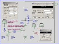
Lineup Audio Lab improved 2SK170 Jfet BOZ version 2.0a
I guess this was not a comment to my posted circuit.
Because I have still, for simplicity, bias at ground without cascode.
I have told this before:
I am not a man 'who cascode anything I see'
I guess Nelson Pass missed my post.
I have no comment to this.
He is often in A Great Hurry (not to miss train to heaven?),
I would imagine
------------------------------------------------
Lineup Audio Lab improved 2SK170 Jfet BOZ version 2.0a
-------------------------------
- Attached is the SquareWave at 10 KHz, with 4Vpeak / 10 kOhm output
- For my basic circuit, see previous post schematic.
Following criteria setup was used, for trimming for optimal performance:
1. Input bandwidth restricted to 3-300000 Hertz, -3dB (no junk outside this will even enter into 2SK170GR
2. LOAD was changed, temporarily to 4k7 = heavier, worst case, load
3. Test frequency input was set to 10000 sinus ( 10KHz)
( on the borderline of what most mature people can hear )
Was found that with these criteria, 2SK170 / 2N5401 combination
works best at slighly higher Voltage, 12-13 Volt, and a bit lower bias, ~7.5mA
(compared to 10.5 Volt / 9mA in my Version 1.0a)
Regards
lineup
----------------------------------------------------------------------------
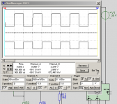
Below is result for trimmed Version 2.0a
Shows the following Simulated Squarewave, at 4 Volt Peak output:
The frequency is 10 kHz Square
hmmm,Nelson Pass said:Yes, the minute you are willing to bias the input at other than
ground you can make for great improvement.
As to the question about cascoding, yes you can, but you no
longer have the load-line cancellation discussed earlier, and
you will have to alter other parts of the circuit.
I guess this was not a comment to my posted circuit.
Because I have still, for simplicity, bias at ground without cascode.
I have told this before:
I am not a man 'who cascode anything I see'
I guess Nelson Pass missed my post.
I have no comment to this.
He is often in A Great Hurry (not to miss train to heaven?),
I would imagine
------------------------------------------------
Lineup Audio Lab improved 2SK170 Jfet BOZ version 2.0a-------------------------------
- Attached is the SquareWave at 10 KHz, with 4Vpeak / 10 kOhm output
- For my basic circuit, see previous post schematic.
Following criteria setup was used, for trimming for optimal performance:
1. Input bandwidth restricted to 3-300000 Hertz, -3dB (no junk outside this will even enter into 2SK170GR
2. LOAD was changed, temporarily to 4k7 = heavier, worst case, load
3. Test frequency input was set to 10000 sinus ( 10KHz)
( on the borderline of what most mature people can hear )
Was found that with these criteria, 2SK170 / 2N5401 combination
works best at slighly higher Voltage, 12-13 Volt, and a bit lower bias, ~7.5mA
(compared to 10.5 Volt / 9mA in my Version 1.0a)
Regards
lineup
----------------------------------------------------------------------------
Below is result for trimmed Version 2.0a
Shows the following Simulated Squarewave, at 4 Volt Peak output:
The frequency is 10 kHz Square
Attachments
Nelson Pass said:As to the question about cascoding, yes you can, but you no
longer have the load-line cancellation discussed earlier, and
you will have to alter other parts of the circuit.
Mr. Pass, can we not cascode it in tune with the load line ala Zv9?
Blues said:can we not cascode it in tune with the load line ala Zv9?
Of course, but my previous comment still applies.
Nelson Pass said:
Of course, but my previous comment still applies.
Ok. On 2nd thought, if we can tune it to the load line without a cascode and we have enough voltage swing with a single jfet...let's keep it simple!
Battery PS would make it a killer...we won't worry on rectified PS noise.
- Home
- Amplifiers
- Pass Labs
- Jfet BOZ