2SK170GR - Spice Model
This is what I use to simulate my 2SK170GR preamplifier circuits.
Is this a decent model?
Are there any other 2SK170 models around .....
Me lineup, and many others, would be grateful to know these models.
As well as good useful models for
those 'other Nelson preamp devices'. Like IRF610 IRF9610
thanks lineup
--------------------------------------------------------------------------------------
From the same Norwegian knut.lib ( OrCAD )
The PNP P-JFET partner of 2SK170:
* http://www.iu.hio.no/~knutn/eldesign/library/knut.lib
.model 2sk170GR NJF(Beta=20m Rs=4.151 Rd=4.151 Betatce=-.5 Lambda=1.923m
+ Vto=-.5024 Vtotc=-2.5m Cgd=20p M=.3805 Pb=.4746 Fc=.5
+ Cgs=25.48p Isr=84.77p Nr=2 Is=8.477p N=1 Xti=3 Alpha=10u Vk=100
+ Kf=111.3E-18 Af=1)
*Modified Beta-value from J2sk170
This is what I use to simulate my 2SK170GR preamplifier circuits.
Is this a decent model?
Are there any other 2SK170 models around .....
Me lineup, and many others, would be grateful to know these models.
As well as good useful models for
those 'other Nelson preamp devices'. Like IRF610 IRF9610
thanks
lineup--------------------------------------------------------------------------------------
From the same Norwegian knut.lib ( OrCAD )
The PNP P-JFET partner of 2SK170:
.model 2sj74GR PJF(Beta=20m Rs=7.748 Rd=7.748 Betatce=-.5 Lambda=4.464m
+ Vto=-.5428 Vtotc=-2.5m Cgd=85.67p M=.3246 Pb=.3905 Fc=.5
+ Cgs=78.27p Isr=129.8p Nr=2 Is=12.98p N=1 Xti=3 Alpha=10u Vk=100
+ Kf=26.64E-18 Af=1)
*Modifisert Beta-verdi fra J2sj74
D&G reversed
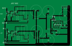
I have to apologize - I have the pinout incorrect on the jfet - I thought it was GDS but it's DGS (stoopid newbie mistake )
)
I'll revise and repost. Sorry about this
Stephen
Edit: Actually, I have the jfet facing backward as well - reminder to self - don't get overexcited and attempt layouts late at night
Edit2: Actually, it's not that it's late at night, it's because I didn't check the datasheet first.
I have to apologize - I have the pinout incorrect on the jfet - I thought it was GDS but it's DGS (stoopid newbie mistake
)I'll revise and repost. Sorry about this
Stephen
Edit: Actually, I have the jfet facing backward as well
- reminder to self - don't get overexcited and attempt layouts late at nightEdit2: Actually, it's not that it's late at night, it's because I didn't check the datasheet first.
Zen Mod said:
Papa already promised to me one X1000 case ,complete with hsinks
( that dreky box will be probably good enough for my next phono preamp), randomly throttle filled with small/medium/big jfet/mosfet goodies ;
he sez-because weight is slightly under 100 killos ,he will pay for shipping.......there is no need that I worry about trivia like this ........

X1000 is ugly
mpmarino said:Hi Twitchie,
I look forward to your completion and impressions. I'm sure I won't get to it for quite some time. Amongst the majority of the company on DIYA I'm a hopeless newb but I think you may want to make room on the board for 10uf film caps. I'm thinking that with so few parts - selection may be more important.
Please free to tell me I'm wrong and I'll happily crawl back into my hole
Thanks for the input mpmarino - I didn't start out thinking I was going to share this layout and did it with a pair of 10uF Blackgate N caps I have that I ordered for a P1.7 (Veteran's boards) in mind.

I allways wanted to see a genuine Tupper-Amp. Nice.cviller said:
How did you know I needed that exact circuit for my lunch-box project???
That saves me a lot of time! Thanks!
manuel
Manu said:
I allways wanted to see a genuine Tupper-Amp. Nice.
manuel
It is actually an amp A/B tester and it works nicely except for the passive preamp feature which is not the way to go when listening to F4...

I had planned to build something based on one of papas preamps, but it was with two 2sk170s and slightly more complicated feedback....
twitchie said:
I thought it was just the input attenuator.
Stephen
it is
stefanobilliani said:Is the pot essential ?
25k pot and 1 Mohm form the input impedance.
The 1 Mohm is there for safety ... in case the glider of the pot loses contact.
If you have, like me, in your CD-Player volume control
you should be able to remove 25k pot.
But the pot has got another task. too:
If you use different sources and the amplifier gain is high (sse my prvious posts! )
Then this pot lets you adjust the level,
so that amplifier Will Not Clip.
Rule, if you keep 25k pot.
1. Put your CD-Player output, to 80-90% of max rotation.
2. Play a record with 'normal' output level. Those your favourites!
3. While keeping the CD volume at 80-90%, adjust 25kOhm pot
for a rather high sound output.
--------------------
Wrong method to set level:
Turning up the 25k very much, and only be able to use your remote CD-Volume to maybe 15-20%
--------------------
Best is of course, to adust the gain of 2SK170 amplifier
to not amplify more than you need.
See my thinking before.
Myself, and most of us, would live happily with a Line Pre Amplifier with a gain around x4.
This value, +12dB, is some sort of 'standard for lineamps.
Regards
lineamp
lineup said:
25k pot and 1 Mohm form the input impedance.
The 1 Mohm is there for safety ... in case the glider of the pot loses contact.
If you have, like me, in your CD-Player volume control
you should be able to remove 25k pot.
But the pot has got another task. too:
If you use different sources and the amplifier gain is high (sse my prvious posts! )
Then this pot lets you adjust the level,
so that amplifier Will Not Clip.
Rule, if you keep 25k pot.
1. Put your CD-Player output, to 80-90% of max rotation.
2. Play a record with 'normal' output level. Those your favourites!
3. While keeping the CD volume at 80-90%, adjust 25kOhm pot
for a rather high sound output.
--------------------
Wrong method to set level:
Turning up the 25k very much, and only be able to use your remote CD-Volume to maybe 15-20%
--------------------
Best is of course, to adust the gain of 2SK170 amplifier
to not amplify more than you need.
See my thinking before.
Myself, and most of us, would live happily with a Line Pre Amplifier with a gain around x4.
This value, +12dB, is some sort of 'standard for lineamps.
Regards
lineamp
Yeah , I understand .
A standard CD output will clip this Pre I believe .
The nice thing is this Pre has High gain -low noise . So it may be very good to turn up the gain of a pre stage like the Pearl .
So using the POT is essential .
Since the question has come up and not answered, the
situation with the gain, bias, and resistor values is as
follows.
The device is self biased, and we want the highest value of
bias possible for lowest distortion which makes us want to
use a low value Source resistor to ground.
At the same time, it would be nice to not have too much gain
by virtue of that Source resistor value. The apparent resistance
of the JFET is about 50 ohms, so the gain into a 10 K ohm load is
about 1000 / 60 which is about 24 dB.
We can get lower gain, but the distortion will increase - it's
all a trade-off. I didn't make any effort to exactly optimize these
values - they were just thumbnail calculations.
Nelson Pass said:......................... I didn't make any effort to exactly optimize these
values - they were just thumbnail calculations.
with all mileage Papa already have , that thumb is certainly more confident than someone's sim
Could this be used as a headphone amp, and would it be possible to run it at say 18V (2 9V batteries)?
I redid the layout and etched it and it is tiny
It could dethrone CMOY in terms of sound and simplicity
Here's the (hopefully) fixed layout
I redid the layout and etched it and it is tiny
It could dethrone CMOY in terms of sound and simplicity
Here's the (hopefully) fixed layout
Attachments
twitchie said:Could this be used as a headphone amp, and would it be possible to run it at say 18V (2 9V batteries)?
...................
too wimpy
- Home
- Amplifiers
- Pass Labs
- Jfet BOZ