Hello all, so I just finished building this seemingly simple circuit. It works well enough but it seems to be current limiting at just over 3 amps.
There is minimal current sag before the regulator, so it's got plenty of gas.
The device is not over heating, barely gets warm at 3 amps. All connections are ok, rechecked today. Any ideas?
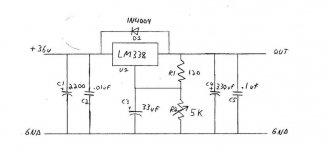
Here's the schematic:
There is minimal current sag before the regulator, so it's got plenty of gas.
The device is not over heating, barely gets warm at 3 amps. All connections are ok, rechecked today. Any ideas?
Here's the schematic:
Attachments
Hi,
regulation seems to have stopped being effective long before you get to 27V out.
At what current does the output start to drop from 32V5 out?
What is the input voltage when the output voltage just starts to drop?
Can your DMM be set to measure AC to check the ripple on the input to the regulator (while still having the 32V5 bias on the ripple signal)?
imix500 said:Output flattens out at 27.7v
Under lesser load it will output a full 32.5v
The input voltage is too low for it to regulate, that's why it doesn't work. C1 is also far too small, although a higher voltage transformer is probably required anyway (and a larger C1).
Ok guys, here is some more info:
Unloaded rail voltage is about 36.1v
The rail voltage at 27v out and current limiting is 32v
I set my dmm to ac and measured 70v ac at the 2200uf cap next to the input of the reg, also at the output. But this must be a false reading of harmonics and such right? (it's not a true rms meter)
Forgot to mention, the main filter cap is 18000uf. The 2200uf is just a smaller one located next to the reg.
Thanks!
imix500 said:
I set my dmm to ac and measured 70v ac at the 2200uf cap next to the input of the reg, also at the output. But this must be a false reading of harmonics and such right? (it's not a true rms meter)
Try putting a capacitor in series with the meter lead (0.1uF should be fine) and try reading again, although it won't read accurately anyway - but many meters read DC on the AC ranges as they don't have internal blocking capacitors.
Peranders, ah yes I always forget about that pesky derating of the transformer with full wave bridge and cap. It's something like 1.8x va is needed right?
The transformer is an industrial control type used for driving pilot lights and contactors and such, (freebie) I'll have to see if I can remeber the va rating but I think it's 150, which would be less than 1.8x.
Nigel, I'll do this when I get home from work tonight.
Thanks!
The transformer is an industrial control type used for driving pilot lights and contactors and such, (freebie) I'll have to see if I can remeber the va rating but I think it's 150, which would be less than 1.8x.
Nigel, I'll do this when I get home from work tonight.
Thanks!
Nigel, put a .1uf ceramic cap in series with the meter and although the meter no longer read ~70v, it wasn't showing hardly anything. Actually the reading started high but quickly fell to .1 or .2v after a few seconds unloaded. Loaded down as much as the reg would allow I could barely get .1v on it. (It's a cheap meter .1v is as low as it will show in ac) Man I miss my fluke 87.
Anyway, here are some documented current and proportional filter cap voltage.
With reg voltage out set to max into a resistor bank:
No load - 37.2v
~1A - 34.8v
~1.5A - 33.9v
~2.5A - 32.6v
Thanks!
Anyway, here are some documented current and proportional filter cap voltage.
With reg voltage out set to max into a resistor bank:
No load - 37.2v
~1A - 34.8v
~1.5A - 33.9v
~2.5A - 32.6v
Thanks!
Hi,
it appears from your voltage readings that the regulator is not regulating. It may be that setting to max is preventing regulation because you are setting the input =output at each load current.
Try again by presetting the adjuster to give an output voltage of 24Vdc into 4k7 load (5mA).
Then note your readings into various test load and also give us the input voltage with each output.
Hi AndrewT, I will try that when I get home tonight.
The voltage readings I gave were pre-regulator, right off the filter cap. However, the "regulated" voltage was dropping at a consistant rate from 1A on as well. My wondering is if the rail voltage sag is too much for the reg to handle as proposed by Nigel, or if it's somthing else.
Thanks.
The voltage readings I gave were pre-regulator, right off the filter cap. However, the "regulated" voltage was dropping at a consistant rate from 1A on as well. My wondering is if the rail voltage sag is too much for the reg to handle as proposed by Nigel, or if it's somthing else.
Thanks.
imix500 said:Hi AndrewT, I will try that when I get home tonight.
The voltage readings I gave were pre-regulator, right off the filter cap. However, the "regulated" voltage was dropping at a consistant rate from 1A on as well. My wondering is if the rail voltage sag is too much for the reg to handle as proposed by Nigel, or if it's somthing else.
Thanks.
Almost certainly sag! - you're feeding it with too little voltage.
Don't forget, the input voltages you're reading are AVERAGED BY YOUR METER - there will be considerable ripple on it, probably dropping below the threshold of the regulator.
As suggested, set it for 24V out, so you have a reasonable margin, and then test it again.
You could really do with a scope, but you probably knew that already?.
Hey Guys, here are some more numbers:
Output set to 24v through 4.7k resistor.
Rail -- Amps -- V Out
37.4 -- 0 -- 24
34.8 -- 1 -- 23.7
34.1 -- 1.6 -- 23.7
33.3 -- 2 -- 23.6
31.8 -- 2.3 -- 23.4
31.4 -- 3.4 -- 23.3
30.9 -- 4 -- 23.2
29.7 -- 5.1 -- 23.1
Nigel, I certainly do need a scope. I used to have an old eico tube scope (still do in storage I think) but I'd love to find a cheap used one.
Thanks!
Eva said:A multimeter reading 70V AC seems like a regulator oscillating (probably due to poor layout or bad capacitive decoupling paractices). I have experienced something similar in the past with two LM338 sharing the same heatsink (I had to use independent isolated heatsinks!).
Cheapest China-multimeters show dc multiplied by two when measuring on ac-scale. I just checked two of my cheapest chinese meters and they both show 19.8V AC (or zero depending on polarity) from 9v battery!
---
Also inserting series cap with measurement lead doesnt work with these cheapo-meters as they use half-wave rectifiers at the input.
Yeah I might have to go get that old scope, and see if it powers up on a variac. (I can't remember why I stopped using it) But I did start looking around on ebay last night.
I would agree at this point that ripple is causing at least a good part of the problem. I noticed that as the load increased at 24v, an audible, but pretty quiet, buzzing from the regulator grew louder and louder. This would be the ripple I'm hearing?
Layout- I'm using a pcb I recently bought from a member here that is meant for to220 devices. I simply put leads on the 338 to connect to the pads for the reg. The leads to the device are about 4in. Everything else (pcb,bridge,cap) is kinda floating in air for troubleshooting.
AndrewT, the table I last posted pretty much shows a good range of current. This is gonna be a general bench power supply so it will be supplying voltages and currents throughout it's capability. If you want me to try different voltage outs or something else let me know.
Thanks!
- Status
- This old topic is closed. If you want to reopen this topic, contact a moderator using the "Report Post" button.
- Home
- Design & Build
- Parts
- LM338 Current Limiting