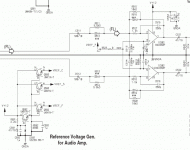
I'm not an EE, not even close. I've been playing around, learning as I go, with the outputstage of a dvd-player. See attachement for the schematic.
I have a question about single power supply for opamps: the virtual ground is controlled by a zenerdiode. The resulting Vdc to the inputpin of the opamp (VREF_F) is about 5.6Vdc, where as it should be exactly half of 12V in theory. Is there any reason to tweak the VREF_F to exactly 6V? Does the performance somehow degrade when the virtual ground isn't exactly in the middle? I figured out I can get 6.00V by changing R592 to about 7-8k ohm while adding a resistor between D591 and Q592 of about 220ohm. If there is something to gain, I will do so, but if it has no impact on soundquality or something important, I'll save myself the trouble.
Btw, apart from influencing the VREF_F a little, what is the purpose of R592? If you make it even higher than the original 680k the VREF_F never exeeds 5.7V. Again, is this close enough, or is it sloppy/efficient designing?
I have a sample of the THS4032 opamp. I've reading 'somewhere' it should be pretty good. Any comment on the soundquality?
Is the choice of opamps restricted by the usage of a simgle power supply? The THS4032 mentiones it in its datasheet, so it should be ok, but I also had a look at the AD8620 which lacks this in its datasheet.
Thanks")
I have a question about single power supply for opamps: the virtual ground is controlled by a zenerdiode. The resulting Vdc to the inputpin of the opamp (VREF_F) is about 5.6Vdc, where as it should be exactly half of 12V in theory. Is there any reason to tweak the VREF_F to exactly 6V? Does the performance somehow degrade when the virtual ground isn't exactly in the middle? I figured out I can get 6.00V by changing R592 to about 7-8k ohm while adding a resistor between D591 and Q592 of about 220ohm. If there is something to gain, I will do so, but if it has no impact on soundquality or something important, I'll save myself the trouble.
Btw, apart from influencing the VREF_F a little, what is the purpose of R592? If you make it even higher than the original 680k the VREF_F never exeeds 5.7V. Again, is this close enough, or is it sloppy/efficient designing?
I have a sample of the THS4032 opamp. I've reading 'somewhere' it should be pretty good. Any comment on the soundquality?
Is the choice of opamps restricted by the usage of a simgle power supply? The THS4032 mentiones it in its datasheet, so it should be ok, but I also had a look at the AD8620 which lacks this in its datasheet.
Thanks
Hans L said:You seem slightly unsure, right?
Not really, I wouldn't consider doing it, I'm sure it won't make any audible difference at all (or any measurable difference either - in normal use!).
http://pubpages.unh.edu/~aperkins/pdf/BA-BU-devices-ROHM/ba4560.pdf
look for common mode input range
sometimes datasheet # need some massaging;
I would take worst case +/-12 vin @ +-15 Vsupply and call the worst case cm range anything greater than 3 V from either rail
look for common mode input range
sometimes datasheet # need some massaging;
I would take worst case +/-12 vin @ +-15 Vsupply and call the worst case cm range anything greater than 3 V from either rail
The ref voltage should be at a level where you'll get symmetrical clipping and normally an opamp has less high (positive) output voltage than negative or near ground in your case. The simple answer is no and the the ref voltage should be around 50% of the supply voltage.Hans L said:The resulting Vdc to the inputpin of the opamp (VREF_F) is about 5.6Vdc, where as it should be exactly half of 12V in theory. Is there any reason to tweak the VREF_F to exactly 6V?
Many more questions
Thank you guys,
that saves me a lot of tiny parts to (de)solder
What about this question:
Does it need to be specifically designed for single power?
A few other questions:
What are the con's and pro's of a higher V power supply? Some say that given the choice (I might want to put in a seperate psu for the analog audio out), the highest possible V is preferred, but somewhere else I read that even if the max ratings are much higher, a 15V-18V limit is recommended because there aren't that many opamps that will operate happily above that V.
While I'm at it...
Why are inductors not used in the audio path of active circuits? One can use a parallel C in the feedback path (parallel to the resistor) from output to input to limit the freq bandwidth and presumably add stability in case of a highish value feedback resistor, but you could also just but a small value inductor on the output. Any reason why (not) to? I think there *might* be added value to the soundquality in constructing an active circuit with no C's in it, just R en L, as C's seem to be generally avoided if possible. If the circuit itself is stable, one could add inductors/ferrit beads at the output to filter out RF if necessary or would you preferably filter it at the input? The application I'm thinking of is using a wideband (MHz) opamp as an audio preamp.
I'm currently playing with an evaluation version of Orcad Spice. Can these kinds of programs show wether oscillation in an opamp may occur? How? For instance I saw a sim of the audio output signal going down in amplitude from 100kHz or so (large feedback C) and after hitting zero V, bumping up with a sharp corner at in the MHz range. Is that the sign of oscillation?
Filled with questions and hoping to learn
Thank you guys,
that saves me a lot of tiny parts to (de)solder
What about this question:
Is the choice of opamps restricted by the usage of a single power supply?
Does it need to be specifically designed for single power?
A few other questions:
What are the con's and pro's of a higher V power supply? Some say that given the choice (I might want to put in a seperate psu for the analog audio out), the highest possible V is preferred, but somewhere else I read that even if the max ratings are much higher, a 15V-18V limit is recommended because there aren't that many opamps that will operate happily above that V.
While I'm at it...
Why are inductors not used in the audio path of active circuits? One can use a parallel C in the feedback path (parallel to the resistor) from output to input to limit the freq bandwidth and presumably add stability in case of a highish value feedback resistor, but you could also just but a small value inductor on the output. Any reason why (not) to? I think there *might* be added value to the soundquality in constructing an active circuit with no C's in it, just R en L, as C's seem to be generally avoided if possible. If the circuit itself is stable, one could add inductors/ferrit beads at the output to filter out RF if necessary or would you preferably filter it at the input? The application I'm thinking of is using a wideband (MHz) opamp as an audio preamp.
I'm currently playing with an evaluation version of Orcad Spice. Can these kinds of programs show wether oscillation in an opamp may occur? How? For instance I saw a sim of the audio output signal going down in amplitude from 100kHz or so (large feedback C) and after hitting zero V, bumping up with a sharp corner at in the MHz range. Is that the sign of oscillation?
Filled with questions and hoping to learn
Re: Many more questions
To be true 'single rail' it does, but the vast majority of opamps fed from a single rail are normal dual rail ones, with a dual rail created from the single rail.
The higher the rails the higher the output level can be, without clipping - but as you're normally only talking about 1V RMS it's not a big problem, and +/-12V gives you plenty of headroom.
Inductors cost money, capacitors are far cheaper, avoiding capacitors isn't anything to get too excited about - like anything 'audiophile' there's an awful lot of rubbish said about it!.
In fact, it's commonplace to use 'gyrators' in audio equipment (graphic equalisers etc.), these use an amplifier and capacitor to 'create' an inductor without actually using one!.
I'm a big unbeliever in simulations - from what I've seen over the years it's commonplace to have to modify the circuit to make the simulation work - in my opinion this makes it completely useless!. For it to be valuable you should be able to simulate any working circuit without any changes at all, and it should work exactly as the real world does - and this doesn't happen!.
However, as long as you're aware of their limitations, it can be a useful exercise?.
Hans L said:
Does it need to be specifically designed for single power?
To be true 'single rail' it does, but the vast majority of opamps fed from a single rail are normal dual rail ones, with a dual rail created from the single rail.
A few other questions:
What are the con's and pro's of a higher V power supply? Some say that given the choice (I might want to put in a seperate psu for the analog audio out), the highest possible V is preferred, but somewhere else I read that even if the max ratings are much higher, a 15V-18V limit is recommended because there aren't that many opamps that will operate happily above that V.
The higher the rails the higher the output level can be, without clipping - but as you're normally only talking about 1V RMS it's not a big problem, and +/-12V gives you plenty of headroom.
While I'm at it...
Why are inductors not used in the audio path of active circuits? One can use a parallel C in the feedback path (parallel to the resistor) from output to input to limit the freq bandwidth and presumably add stability in case of a highish value feedback resistor, but you could also just but a small value inductor on the output. Any reason why (not) to? I think there *might* be added value to the soundquality in constructing an active circuit with no C's in it, just R en L, as C's seem to be generally avoided if possible. If the circuit itself is stable, one could add inductors/ferrit beads at the output to filter out RF if necessary or would you preferably filter it at the input? The application I'm thinking of is using a wideband (MHz) opamp as an audio preamp.
Inductors cost money, capacitors are far cheaper, avoiding capacitors isn't anything to get too excited about - like anything 'audiophile' there's an awful lot of rubbish said about it!.
In fact, it's commonplace to use 'gyrators' in audio equipment (graphic equalisers etc.), these use an amplifier and capacitor to 'create' an inductor without actually using one!.
I'm currently playing with an evaluation version of Orcad Spice. Can these kinds of programs show wether oscillation in an opamp may occur? How? For instance I saw a sim of the audio output signal going down in amplitude from 100kHz or so (large feedback C) and after hitting zero V, bumping up with a sharp corner at in the MHz range. Is that the sign of oscillation?
I'm a big unbeliever in simulations - from what I've seen over the years it's commonplace to have to modify the circuit to make the simulation work - in my opinion this makes it completely useless!. For it to be valuable you should be able to simulate any working circuit without any changes at all, and it should work exactly as the real world does - and this doesn't happen!.
However, as long as you're aware of their limitations, it can be a useful exercise?.
- Status
- This old topic is closed. If you want to reopen this topic, contact a moderator using the "Report Post" button.
- Home
- Design & Build
- Parts
- Single supply opamp - unequal rail voltage and opamp selection