I guess the capacitance test should be a good screening for MOSFETs too. It's virtually impossible to get low Cgs from high powered devices and vice versa.
OK, just did a rough thermal test;
sandwiched and clamped a TO246 between 2 identical copper plates, used thermal grease, and put 30W through it.
Back plate rose by 32 deg C.
Front plate rose by 14 deg C.
With front plate removed, back rose by 38 deg C.
So, any heat removed from the epoxy side, is heat well gotten rid of, IF the mounting geometry allows the space for it.
--------------------
I'm contemplating coming to the dark side...
What kind of cookies to you have?
Most of the heat is going down the leads, don't count on much going through the epoxy.
OK, just did a rough thermal test;
sandwiched and clamped a TO246 between 2 identical copper plates, used thermal grease, and put 30W through it.
Back plate rose by 32 deg C.
Front plate rose by 14 deg C.
With front plate removed, back rose by 38 deg C.
So, any heat removed from the epoxy side, is heat well gotten rid of, IF the mounting geometry allows the space for it.
--------------------
I'm contemplating coming to the dark side...
What kind of cookies to you have?
Hi Andy,
I'm not sure what your test proves (still thinking about it) - given that the heatsink dissipation area got reduced by having only the back heatsink.
Oh, ok... IF you can't increase the thermal efficiency of the back heatsink (due perhaps to space limitations), then what this experiment says is that you can get a bit more dissipation if you do mount a heatsink up front.
Cheers!
Clem
ps: what if you mount the Front and Back heatsinks together and mount the back of the transistor to these two combined areas? What is the temp rise then?
It doesn't prove anything.
It suggests that you can remove additional heat.
Increasing the size of the back heatsink gives diminishing returns after a point, because heat has to travel FARTHER, to reach the outer the edges of the sink. The farthest fins are not as effective as the ones closest to the chip.
Removing heat close to the source provides greatest conduction (once you get past the epoxy barrier of course).
Don't sweat it. You'll probably never need to do this. It's just a crazy idea.
vectorplane said:Don't sweat it. You'll probably never need to do this. It's just a crazy idea.
For the record, I don't think its a crazy idea.
OTOH there are a lot of variables involved, including the heatsink geometry. Audio people should take notice of heatsinks designed for new-generation CPUs, where 80W is concentrated on a conduction surface not much larger than 1/3"x1/3". Keeping a processor with that much power to 50 degC is no small engineering feat, given the limitations of the heatsink weight and size. Well, of course it uses a fan...
")
Cheers!
Using CPU heatsinks in audio amps will probably provide more effective heat removal, because those HS's are engineered for a critical application, whre the CPU will die very quickly if not cooled enough.
If you leave the fan in, you'll probably end up with a very compact audio solution.
You don't need to run the fan at full speed ( noise!!

 ). Half or quarter speed can keep it dead quiet and still retain effectiveness.
Andy
If you leave the fan in, you'll probably end up with a very compact audio solution.
You don't need to run the fan at full speed ( noise!!
). Half or quarter speed can keep it dead quiet and still retain effectiveness.Andy

Hi Guys, just passin through and thought I'ld comment, FYI. After checking out what I would need for a heatsink for my Class A, other than the salvage places, there is nothing as afordable as a processor H.S. system. I have 2 "Tower 112" pure copper heat pipes waiting to be attached to 4 paralell Push Pull FET stacks per Ch.. That will be about 120W continuos per. Cost me total, about $90US including the fans.
Then of coarse, They will be sticking up in plain site to oogle at and ask questions about, similar to most artistically constructed tube amp chasis... BTW, you probably realize, copper is almost twice as good at taking away that heat as aluminium. Just my thoughts, Thanks.
Then of coarse, They will be sticking up in plain site to oogle at and ask questions about, similar to most artistically constructed tube amp chasis... BTW, you probably realize, copper is almost twice as good at taking away that heat as aluminium. Just my thoughts, Thanks.
OT
Indeed..
PC Overclockers have been saying for years that a combination of Cu and Al is best for removing heat. Something about copper conducting better, and aluminum releasing heat better. The statements were not scientifically formulated so I thought it was gibberish.
They've been right all along.
Copper has twice the conductivity of Al, but 40% more heat capacity, which means it will act as a storehouse (reservoir) for heat instead of releasing it quickly. Al is best at releasing heat. So the optimal combination would use a solid copper plate or backbone, to conduct heat away and distribute it to all parts of the heatsink; and Aluminum fins, to release the heat quickly.
It's a real hassle to build something like that (either that, or it's expensive), but I'm sure the results would be unsurpassed.
Andy
OT - but thats ok
Hi Andy,
Agree with your comments, but have always wondered about the interface between copper and aluminum - what losses there are, as far as heat conduction. I'm using a pure-copper HS on my system, I get the impression its better than an earlier copper-aluminum HS. But, there are a lot of other variables I suppose so its really hard to decide...
Cheers!!
Clem
I think copper and Al don't weld together well. so the interface would have to be just pressure contact with perhaps some thermal grease. Mating surfaces would have to be lapped and polished smooth.
But then again, mating surfaces would need to the lapped smooth for transistor-to-heat sink contact also. Judging by the dents and scratches I see on some power transistors (on the mating surface), the guys in the factory must have been having transistor fights with them, before shipping them out.
I remember some overclocking reviewers had split apart some Cu-Al heat sinks, and found, to their disappointment, that the two were literally glued with (thermal) epoxy, the mating surfaces were rough and uneven, and the glue had left voids inside. It's perfectly possible to buy a Cu-Al HS that's poorly made, and where the bi-metal combination is used just as a marketing ploy.
The only sure way is DIY. Get a 1/4" Cu plate, bolt the semiconductor in the middle, and bolt several Al CPU heat sinks onto the copper all around it.
Should work well. Only way to know is to try...
Andy
Should work well. Only way to know is to try...
[/B]
Go for it! I'll have to wait for the next major school break to get anything done.... :-(
Cheers!
Clem
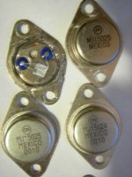
Hey nando,
hope this help, first two are original Motorolas from an altec lansing amp I repaired, notice the big die and two colletor wires.
the two at the bottoms are original ON semi samples from my brother who works as an engineer fro ON Semi. Will take a pic of fake Mot on my next post.
Ecs21
hope this help, first two are original Motorolas from an altec lansing amp I repaired, notice the big die and two colletor wires.
the two at the bottoms are original ON semi samples from my brother who works as an engineer fro ON Semi. Will take a pic of fake Mot on my next post.
Ecs21
Yes, I opened many transistors, and I know the diference inside between the original ones and the fakes...
But, how do I know if they're fakes or not when I'm buying them??
Testing? SOA is out, I can not burn their fake transistors...
Still in the air... Any good method to indentify?
I read some time ago about HFE here, did you guys found any thing related with hfe and fakes?
Thaaannkkssss !
But, how do I know if they're fakes or not when I'm buying them??
Testing? SOA is out, I can not burn their fake transistors...
Still in the air... Any good method to indentify?
I read some time ago about HFE here, did you guys found any thing related with hfe and fakes?
Thaaannkkssss !
- Status
- This old topic is closed. If you want to reopen this topic, contact a moderator using the "Report Post" button.
- Home
- Design & Build
- Parts
- Fake *******ING "MOTOROLA" Transistors