Here's the new thread for discusion of the difference between bi-wiring and mono wiring.
The basic premise for the analysis is this: When a speaker wire carries an audio signal to a crossover, is there a non linearity in transfer function as a result of the branching of currents at the crossover.
I'll get to definitions on a later post, with pictures or diagrams. For now, I recommend limiting this thread to the technical analysis. Should this analysis have proven, measureable validity, then perhaps listening issues can be discussed.
Any validation testing must be via equipment with resolution at least 10 times the entity being tested.
Oh, almost forgot the most important thing..question ALL assertions, equations, and conclusions. This is a discussion, not a sermon. It is preferable that errors be called when spotted...and we all make errors..
Cheers, John
Linear Systems do not "create" Nonlinear Distortion
1st rule of linear system theory: linear systems do not create nonlinear distortion products of their excitation signals
if wire, crossover and speakers are modeled as linear R,C,L and constant mutual couplings then they are a linear load and do not create distortion no matter how few/many branches you divide the wiring up into
bi-wiring can reduce mutual impedance coupling where current from one driver imposes a voltage on the (linear) mutual impedance and changes the voltage seen by the other driver - but the eq are all linear- - superposition works perfectly
you have to assume a source of nonlinearity in the system for an analysis of distortion to make sense
drivers are of course not linear; voice coil inductance, BL product, surround spring constant are all nonlinear and time varying to some degree - at a much lower level wire tempco causes nonlinear response with power dissipation
as a quick guess if wire is ~100 mOhms vs loads of ~8 Ohms I would expect distortions from one driver's nonlinear current demand to be attenuated by ~.1/8, nearly 40 dB before reaching the other driver and then only distortion products in the pass band would be reproduced
further, nonlinearity in dynamic drivers is mostly related to displacement which is largest at the bottom of its frequency range, assuming several octaves of bandwidth the largest distortion products are in the distorting driver’s own bandwidth and only very small higher order distortion products are present to be coupled to the next higher driver's passband
alright already, I spell checked it this (last) time
Re: Linear Systems do not "create" Nonlinear Distortion
To that end, I have explained to some of my collegues the dillemma I have "uncovered". They typically will find errors I make, but so far, this issue has not been, um, trashed..
Perhaps you should go peruse the "audio lies thread", to understand what it is we are talking about.
So far, analysis using tried and true concepts still gives the distortion. I am in the middle of configuring a scanner in another room, but will post scans of my "chicken scratches" to give you a better feel for what I am talking about.
") )
)
Thank you..
Cheers, John
Agreed, that is indeed a rule of linear systems. Having had that taught me back in the old days, I have had significant issues with the analysis I have performed as of late.jcx said:1st rule of linear system theory: linear systems do not create nonlinear distortion products of their excitation signals
To that end, I have explained to some of my collegues the dillemma I have "uncovered". They typically will find errors I make, but so far, this issue has not been, um, trashed..
Perhaps you should go peruse the "audio lies thread", to understand what it is we are talking about.
So far, analysis using tried and true concepts still gives the distortion. I am in the middle of configuring a scanner in another room, but will post scans of my "chicken scratches" to give you a better feel for what I am talking about.
That argument is not the same thing as what I am speaking. For my analysis, the amp can have zero impedance.jcx said:bi-wiring can reduce mutual impedance coupling where current from one driver imposes a voltage on the the (linear) mutual impedance and chages the voltage seen by the other driver - but the eq are all linear
That is what I was also taught. It may be that the "teachers" were incorrect. If so, I will be upgrading their understanding..if not, hey, I've been incorrect before...that's in my job description (and I take my job seriouslyjcx said:you have to assume a source of nonlinearity in the system for an analysis of distortion to make sense
)That is why I asked "phase accurate" to model the system without the non linearities he used for the drivers..to clear the analysis.jcx said:drivers are of course not linear; voice coil inductance, BL product, surround spring constant are all nonlinear and time varying to some degree - at a much lower level wire tempco causes nonlinear response with power dissapation
Thank you..
Cheers, John
Hi Neutron,
I have one point to ponder here:
I think in some ways the initial anaysis was based on the superpositon of power... and I don't recall ever doing that.
Consider the following, we apply a sine voltage to a cable with a resistive termination, a sine current flows, and power is dissipated in the cable (resistor). Now superimpose another sine of equal frequency, and magnitude, but opposite phase on that system... no voltage, no current, no power.
Follow me here?
poobah said:Hi Neutron,
I have one point to ponder here:
I think in some ways the initial anaysis was based on the superpositon of power... and I don't recall ever doing that.
Consider the following, we apply a sine voltage to a cable with a resistive termination, a sine current flows, and power is dissipated in the cable (resistor). Now superimpose another sine of equal frequency, and magnitude, but opposite phase on that system... no voltage, no current, no power.
Follow me here?
With only one loop to deal with, there is no branch. This is why a single driver with no crossover will not have this issue; it is only the branching that I'm speaking of.
The whole crux of the branching issue is that the instantaneous power loss in the cable resistance no longer tracks the load dissipations for each driver. Something's gotta give..
Cheers, John
Thanks Sy.SY said:If there's any posts from the other thread that you'd like me to split out and move over here, I'll be happy to do so. Or you could just post a link to any of the relevant stuff.
Just let me know...
Cheers, John
Unfortunately I lack the education you gentleman posses, but it doesn;t make me any less inquisitive... yesterday I saw a picture which was, if I understand it correctly, trying to convey that low frequency signals pass through the cable almost uniformly except for a small area in the centre.... as the frequency moved up the current would become thiner and thiner layer until its just a skin.... I think the bottomline of the page was the for higher frequencies its better to have two thinner wires than one thick one... does this have any bearing on Biwiring?
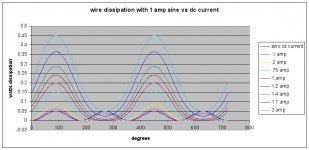
Here's a graph showing the dissipation within the cable as a function of the dc current flowing through it. The sine is 1 ampere, and the resistance of the cable is .05 ohms, consistent with a 10 foot run of #12 zip, and neutrik connectors on each end..connector is 3 milliohms per contact, #12 runs 2 milliohms per foot, single conductor...times 2 gives total wire resistance.
The peak power with just the sine is 1 amp squared times .05 ohms, or 50 milliwatts, which happens at 90 degrees.. Since the negative side of the waveform also dissipates, it peaks at 50 mW at 270 degrees. This is shown by the blue line on the graph, the zero dc current line.
With one ampere of dc plus one ampere of ac, look at the 90 degree point...the current there is 2 amperes, and the dissipation in the cable is now 200 mW, while at 270 degrees, the dissipation is.....ZERO..
The time varying lossed within the wire resistance are getting larger with the DC current applied.. As the current is increased, the power dissipation has less and less 2x freq profile, and more and more base freq profile..
So, what gives
Cheers, John
ps..I hate those jpeg artifacts..100 kilobytes is too small..
Attachments
No. you refer to skin effect. It happens because all conductors try to push a changing current towards the outside. It has always been calculated incorrectly for audio frequencies, and has not been measured correctly..but that is another thread.Nordic said:Unfortunately I lack the education you gentleman posses, but it doesn;t make me any less inquisitive... yesterday I saw a picture which was, if I understand it correctly, trying to convey that low frequency signals pass through the cable almost uniformly except for a small area in the centre.... as the frequency moved up the current would become thiner and thiner layer until its just a skin.... I think the bottomline of the page was the for higher frequencies its better to have two thinner wires than one thick one... does this have any bearing on Biwiring?
This thread is about the woofer and tweeter current not "playing well together" because they are forced into the same wire.
As jcx pointed out, we were taught that it shouldn't make a difference. But I so far, have shown a mechanism which says it does..and I present it here for all to take potshots at..peer review, so to speak.
Cheers, John
Unfortunately I lack the education you gentleman posses, but it doesn;t make me any less inquisitive... yesterday I saw a picture which was, if I understand it correctly, trying to convey that low frequency signals pass through the cable almost uniformly except for a small area in the centre.... as the frequency moved up the current would become thiner and thiner layer until its just a skin.... I think the bottomline of the page was the for higher frequencies its better to have two thinner wires than one thick one... does this have any bearing on Biwiring?
If skin effect is all that matters here and is significant, you really wouldnt need to "biwire" with seperate wires for woof and tweet. Parallel wires for (and connectors?) for both would have the same effect.
jneutron said:Here's a graph showing the dissipation within the cable as a function of the dc current flowing through it. ....
John:
Please attach your spreadsheet file. You have something wrong, linearity works.
Rodolfo
Darn* it, I know...something is wrong..ingrast said:
John:
Please attach your spreadsheet file. You have something wrong, linearity works.
Rodolfo
I've been tryin to find it for weeks now..
The full sheet is 947 kilo in size..
Let me see if I can cull it down and still keep it useful. For some reason, copying cells to another worksheet doesn't keep the equations..
Cheers, John
Thanks. When I tried that,it gave me the choice of text or unicode text. Neither seemed to work, but I'm in a hurry now, carpool and all.Nordic said:Instead of clicking paste, click paste special, this allows you to copy the formulas too...
Make sure to delete empty datasheets to reduce size...
Cheers, John
poobah said:OK John,
Now take your power waveform in post 9 and throw it on a resistor... do you not get a votage sinewave with offset? ... pure?
We are being deceived by the shape of the power waveform merely because we are not used to looking at them?
Looking at the power dissipation is indeed confusing. What nags me is the fact that the power swing gets larger, even though the ac excitation current remains the same..only the dc is changing..
For my premise to be correct, geeze...linearity would hafta be violated, FFT's would hafta miss the distortion...maybe superposition???weird.. too many barriers...that's why I've been bustin my butt trying to find my errors..my assumption is that there is an error somewhere, I just can't find it..
Cheers, John
- Status
- This old topic is closed. If you want to reopen this topic, contact a moderator using the "Report Post" button.
- Home
- Design & Build
- Parts
- Bi wiring/single wire distortion thread