If I'm using a regulator for the heaters, should I put the majority of the filter capacitance before or after the regulator?
I have about .45A in total which, I think, means I should be using about 4700uF.
Also, is there any major difference in audio quality between 6.3 and 12.6V in the real world?
12.6V seems easier to implement in this amp, just wondering if I'm going to break some sacred law by doing so!
I have about .45A in total which, I think, means I should be using about 4700uF.
Also, is there any major difference in audio quality between 6.3 and 12.6V in the real world?
12.6V seems easier to implement in this amp, just wondering if I'm going to break some sacred law by doing so!
John,
Look at it as an attenuator. The series impedance before the capacitor, and the capacitor to gnd, form a divider for the unwanted ripple and noise. Got it so far?
Now, the impedance *after* the regulator is the output impedance of the regulator, which is very, very small compared with the impedance of the raw supply before the regulator. Therefor, the attenuating action of a certain cap *after* the reg is much less than after the raw supply/ before the reg. So, the greatest effect is with the cap *before* the reg.
Of course, as you know, you still need *some* cap after the reg for reg stability reasons.
Jan Didden
Yes indeed. But talking about THE impedance can hide the fact that it is a complex impedance, with inductive and capacitive components, changing depending on line voltage, load, maybe even the quarter of the moon. So, the attenuator model is a nice way to visualise the effects, but it is not just a single number.
Jan Didden
Jan Didden
Thanks again Janneman,
Do the LM317 type regulators have any start up lag? I remember seeing somewhere that one three pin regulator I was looking at required a minimum input capacitance. I'm only excercising my mind but I was thinking that perhaps without any input capacitance, with it all on the output say, the regulator might have a hard time stabilising the raw rectified DC pulses due to some kind of regulation startup lag. I know it's much more pronounced with circuits like SMPS, which can take a few seconds to fully stabilise.
If I wanted to use a similar supply for a variable bias, can I apply the same general 10,000uF per amp of current rule? So say I have four variable resistors on the output, I'd want to size them so they drew roughly the regulator's max minimum load current, ~5ma. That'd mean around 50uF of filter capacitance. I guess with such low voltage capacitors being so cheap, anything more than this would be fine right?
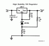
I was looking through National's LM317 datasheets and noticed the attached image.
It uses a voltage reference diode in the Adj chain to add stability, The program resistor, diode and R3 make sense, but I'm a bit confused as to what R2 is doing.
Can someone quickly run me through what is happening to create the 10V output in this schematic so I'm 100% sure?
It uses a voltage reference diode in the Adj chain to add stability, The program resistor, diode and R3 make sense, but I'm a bit confused as to what R2 is doing.
Can someone quickly run me through what is happening to create the 10V output in this schematic so I'm 100% sure?
Attachments
A major consideration is that, for the regulator to regulate, the ingoing voltage must always be at least a couple of volts more than the desired output. So the entry-side capacitance has to be sufficient to reduce 100/120Hz ripple at load current to a point where the trough voltage fits that bill.
- Status
- This old topic is closed. If you want to reopen this topic, contact a moderator using the "Report Post" button.
- Home
- Design & Build
- Parts
- Simple linear regulator question
