I read recently (on one of these forums I think) that although Black Gate N etc are non-polar, there is nevertheless an "ideal" way of wiring them; i.e. long leg or short leg to earth. I can't remember which way was suggested, and I've done the search thing. Can anyone point me in the right direction?
Cheers!")
Cheers!
Peter Daniel said:
Short pin marks the start of the foil, and I prefer to have the outer foil on the ground (at least with positive supply).
Accordingly, I prefer to have the outer foil on signal output.
Thanks Peter. So the start of the foil is NOT the outer foil?
falcott said:
Thanks Peter. So the start of the foil is NOT the outer foil?
That would be my understanding
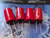
but even if it's not the case, long lead on ground (with pos supply) sounds better to me. I tested it extensively in a DAC.Over weekend I was experimenting with N type 4.7uF 50V caps.
I was comparing a dielectric absorption of N type to F type in different connections. I have found that N type caps are somewhat directional. With connection of short leg to plus and long leg to minus of a 6V battery DA is much higher, almost double in comparison to the oposite polarity connection. I measured 21-24mV and 11-13mV respectively.
I was comparing a dielectric absorption of N type to F type in different connections. I have found that N type caps are somewhat directional. With connection of short leg to plus and long leg to minus of a 6V battery DA is much higher, almost double in comparison to the oposite polarity connection. I measured 21-24mV and 11-13mV respectively.
There some info (and some seriuos claims)
on their site :
http://www.blackgate.jp/ebg6.htm
Just my 0.01$
(no thread's complete without a noob postin a link ehh )
/ Kenny
on their site :
http://www.blackgate.jp/ebg6.htm
Just my 0.01$
(no thread's complete without a noob postin a link ehh
)/ Kenny
Here is the part of that advertisement.
"What is the "Super-E-Caps"?
--------------------------------------------------------------------------------
A pair of nonpolarized Black Gate electrolytic capacitors are particularly connected in parallel or in series so that each one of the capacitors cancels the internal magnetic flux generated by the other, thereby completely eliminating internal resonance and decreasing total impedance to absolute zero as the frequency increase."
I have tried parallel (aka Super-E-caps)and serial connections of N type caps. Again I have tested them for dielectric absorption.
Parallel connection have not produce any visible improvements, however serial connection gave reduction in DA about 10-15% .
In addition to that two N type caps connected in serial like
S-L-L-S or L-S-S-L seem to have no direction (polarity) any more.
"What is the "Super-E-Caps"?
--------------------------------------------------------------------------------
A pair of nonpolarized Black Gate electrolytic capacitors are particularly connected in parallel or in series so that each one of the capacitors cancels the internal magnetic flux generated by the other, thereby completely eliminating internal resonance and decreasing total impedance to absolute zero as the frequency increase."
I have tried parallel (aka Super-E-caps)and serial connections of N type caps. Again I have tested them for dielectric absorption.
Parallel connection have not produce any visible improvements
, however serial connection gave reduction in DA about 10-15% .In addition to that two N type caps connected in serial like
S-L-L-S or L-S-S-L seem to have no direction (polarity) any more.
Iliya said:Here is the part of that advertisement.
"What is the "Super-E-Caps"?
--------------------------------------------------------------------------------
A pair of nonpolarized Black Gate electrolytic capacitors are particularly connected in parallel or in series so that each one of the capacitors cancels the internal magnetic flux generated by the other, thereby completely eliminating internal resonance and decreasing total impedance to absolute zero as the frequency increase."
That is, without any doubt, the most unadulterated piece of pure marketing BS I have seen in a long time. It was written by an idiot.
Teach them a lesson. Don't buy the product.
I_F
Teach them a lesson. Don't buy the product.
First of all it's kind of late to do that as Black Gate caps are no longer made. The second I have mesured them (F-type and N-type) and found that their DF is much lower than other brands including famous Nichicon Muse KZ and Panasonic FC. For example F-type 4.7uF 50V have DF of only 1.5-1.6%. That's really low for electrolytic cap. No doubt about it. The DA of Black Gate caps also measured somewhat lower but not that significantly. So the conclusion is that the BG caps are better. Does their quality justifies their price? That's another matter.
The reason I have placed my findings here on the forum is to learn opinions of other members about use of N-type BG caps. Another question I have if the serial connection of polar BG (FK) caps is equal/better/worse than a non-polar caps (N).
Thank you for the information. I have read only one article by Cyril Bateman. If I remember it right it's called "Amplifier and Capacitor Distortion". Also in the article Cyril recommended to use non-polar caps instead of polarized and if voltage on capacitor exceeds 0.5VAC then use two non-polar caps in series. However in that article he have not mentioned anything at all about back to back serial connection of polarized caps. What particular article you are refering to? I might purchase it as well.
The reason for my confusion about non-polar vs serial connection of polarized is based in test results that I got while testing BG caps.
First I have tested caps for DF using TENMA 72-960 LCR meter. Here are the average results:
Serial connection 2x4.7uF/50V F-type DF=1.5%
Serial connection 2x4.7uF/50V N-type DF=6.0%
Single 4.7uF/50V F-type DF=1.6%
Single 4.7uF/50V N-type DF=5.5%
Then I have tested them for DA. The test setup: 6V (4xAA) battery, 1kOhm resistor, three position SPDT toggle switch, Fluke 85-III DMM. I was charging caps directly from the battery for 10 sec. Then discharging into resistor for 10 sec. After that I was setting capacitor free and measuring maximum residual voltage.
Here are the average results of multiple tests:
Serial connection 2x4.7uF/50V F-type DA=11.0mV max
Serial connection 2x4.7uF/50V N-type DA=10.6mV max
Single 4.7uF/50V N-type connected as Long to Minus and Short to Plus DA=19.4mV max
Single 4.7uF/50V N-type connected as Long to Plus and Short to Minus DA=12.4mV max
From my measurements it seems that the serial connection of two F-type caps gives better results in terms of DF and DA than a single N-type cap. And in addition to that N-type caps exhibit some sort of a non-symmetrical (polarized) behaviour during DA test.
Serial connection of two N-type caps shows somewhat lower DA but much higher DF than F-type.
I am curious why one non-polar N-type cap would give lower distortion than a pair of F or FK-type caps. I guess my next step might be a series of cap distortion tests if I will be able to convince our electronics engineers at work to make them.
Regards.
Hi Ilya,
Interesting results. Just curious, were the Black Gates 'charged' as per manufacturer's recommendations before measurement? Supposedly the construction differs enough from that of electrolytics to require a few days of applied voltage to bring BG's up to operating spec.
Interesting results. Just curious, were the Black Gates 'charged' as per manufacturer's recommendations before measurement? Supposedly the construction differs enough from that of electrolytics to require a few days of applied voltage to bring BG's up to operating spec.
http://www.diyaudio.com/forums/showthread.php?postid=96875#post96875
i recall seeing a web site too
bateman's basic argument is that polar electros have one foil with a spontaneous oxide film with only a few V breakdown V, the resulting high V stess causes distortion - nonpolar electros have full thickness oxide films grown on both electrode foils and therefore have much lower V stress across the oxide dielectric
First I would like answer to rdf. No I have not charged/"formed" the capacitors before test. However the polarized caps already showing better results than non-polar ones anyway. And I have no idea how to "form" the non-polar caps. What polarity should be used?
Now to jcx: thank you for the usefull link. It seems that it would be beneficial for me to get some more of those Bateman articles. Could you recommend any particular article issue regarding performance of Black Gate caps and comparison between non-polar and serial connection of polarized caps. Cyril Bateman has published quite a few articles by now and the copies are not that cheap. Last time I have paid more than $7 for the 4 page article.
Best Regards,
Iliya
Jelemax says '30 hours of applied voltage':
http://www.blackgate.jp/ebg2.htm
Audio Note says 3000 hours , scroll down to 'Idling Process':
http://www.audionote.co.uk/kits/cap_black_gate.htm
Neither really specifies the voltage level or type. A good guess would be a typical circuit voltage for given maximum rating. For a 50 VDC cap for example, connecting it to a 16 VDC or 24 VDC wall-wort supply for a week doesn't sound too misrepresentative. You already have the baseline, if the second result shows no change after a period five times that specified by the manufacturer there's reasonable suspicion it never will.
http://www.blackgate.jp/ebg2.htm
Audio Note says 3000 hours
, scroll down to 'Idling Process':http://www.audionote.co.uk/kits/cap_black_gate.htm
Neither really specifies the voltage level or type. A good guess would be a typical circuit voltage for given maximum rating. For a 50 VDC cap for example, connecting it to a 16 VDC or 24 VDC wall-wort supply for a week doesn't sound too misrepresentative. You already have the baseline, if the second result shows no change after a period five times that specified by the manufacturer there's reasonable suspicion it never will.
Dear rdf,
Thank you for the info. I guess I can try that procedure. 3000 hours suggested by audionote seems to be somewhat excesive. That's more than lifetime of regular electrolytic cap!
However it still not quite clear to me what voltage to use for non-polar N-type caps. Should I just run some low current AC?
The problem is that while I was testing them for dielectric absorbtion I have found strange phenomenon of charge accumulation in one polarity connection. In other words if I was testing cap(s) connected one way, time after time I was getting more or less the same results (residual voltage). But! If the capacitor(s) were tested in the opposite polarity connection after each measurement the caps were showing higher and higher residual voltage. And I am talking here about "non-polar" caps that I assumed should exhibit more or less symmetric behaviour!
Here are some results of my DA measurements:
N-type sample #2 Connection Long to positive, Short to negative
Residual voltage in mV: 8.6 10.8 14.0 13.6 12.0
Reverse polarity(L-,S+):17.5 17.1 22.7 26.2 25.4
N-type sample #3 Connection Long to positive, Short to negative
Residual voltage in mV: 8.8 10.6 9.7 11.8 12.3
Reverse polarity(L-,S+):11.5 12.5 14.3 21.3 23.9 23.6 24.7 24.1 23.2 24.2 25.1
Then on sample #3 polarity was reversed once more to L+, S-.
Residual voltage in mV: 7.9 12.0 11.2 13.4 11.9 12.3 13.4 13.1
I have not documented all the results but I do recall seeing readings as high as 35mV and it was really dificult to discharge the cap to 0V. It was holding charge even after a minute or two of discharging. Again that problem only occured for one connection polarity.
I've come to the conclusion that while the N-type caps do not get damaged by reverse polarity voltage as polar type caps do, they are still showing some sort of the polar behaviour and probably need to be used in pairs in serial connection. That connection exhibits more or less stable good results in DA test. The only problem I see for my application that I need to replace 100uF 25V cap. And there is no 220uF N-type caps with voltage higher than 6.3V.
Another issue that bothers me is the DF of N-type caps that is more that 3 times higher than F(FK?) type. As I recall I've measured 5.5% vs. 1.5%. I do not know if the DF really matters for a coupling application.
Regards,
Iliya
Hi Iliya,
Sorry it took so long to reply, I've been on the road for work/vacation the last few days and just spent another day beating the folk's computer back into submission after my last visit. Oh the xmas season. Those are interesting/scary results for sure and may explain why some on the forum prefer specific orientations on the non-polars. See the Peter Daniel posts for example.
Regarding the proper procedures for testing it's anyone's guess. Rubycon is an extremely reputable manufacturer (look on any motherboard!) so technical explanations on their site I'd take at face value. Jelemax, well that's a different story and theirs read more as marginally coherent marketing than valid technology. Both state emphatically that Black Gates are not electrolytics and require special handling in the form of long charge periods or 'always on' applications. Since you have a specific application in mind, have you considered testing the caps under those conditions? E.i. same voltage/current? Is it PS bypassing or coupling? If the latter bias the BG and capacitor couple a Walkman or boombox across it and let it rip for a few days. From my perspective at the end of the day it's your specific application that matters. I'ld be curious what you find if you're still pursuing it.
URL is death. But still available by webarchive:There some info (and some seriuos claims)
on their site :
404 Not Found
Just my 0.01$
(no thread's complete without a noob postin a link ehh
/ Kenny
Jelmax H.P. BlacK Gate6 page english
Concerning this caps I have a question:
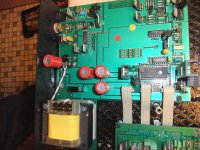
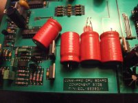
After open a cd player from Micromega (Duo with CDM-9 mechanism) I note, that three capacitors between rectifier and 5V regulators was replaced by Rubycon Black Gate Nonpolar (1500uF/10V - have a look to the attachment).
Until now I always thought that this type of electrolytic capacitor was meant to be placed in the signal path and not after a rectifier.
Was my estimate wrong ?
Attachments
- Status
- This old topic is closed. If you want to reopen this topic, contact a moderator using the "Report Post" button.
- Home
- Design & Build
- Parts
- Non-polar Black Gate capacitors