Pass DIY Addict
Joined 2000
Paid Member
I'm trying to follow Rod Elliot's instructions for making an Expanded Scale Voltmeter and I need a little bit of help and/or confirmation, please.
I have an analog meter that has a printed scale from 100vAC to 130vAC that I'd like to use to measure AC mains voltage. I am hoping someone can confirm my calculation of Rz which biases the zener diode in the attached schematic.
Here is what I have so far:
The meter coil measures 216R. Full scale deflection requires 87.3mV at 0.4mA.
I'll rectify the 120vAC mains voltage to DC, so the 100v to 130vAC range printed on the meter faceplate translates to a range of 141v to 183vDC, thus I have a 42vDC range to work with. I have calculated the value of Rmult as 42v/0.4mA = 105k ohms. For adjustment, I plan to use a 100k fixed resistor in series with a 10k pot.
To be able to measure DC voltages from 141v to 183v (and ignore voltages below ~141v), I was going to use two Zener diodes in series (100v + 39v). I am unsure about how to calculate the value of Rz so that it places a ~10% current load on the Zener stack. Rod indicates to use Ohms Law, but I am unable to duplicate his calculation of 470R for his example and implement it with my own set of numbers.
Is the following correct?
If I use 1w Zeners (100v + 39v), the maximum current draw will be 1w/139v (lowest measured voltage) = 7mA (max rating of 1w zener). Looking to limit current draw to 10% of this figure, my target should be a current draw of 0.7mA.
Using Ohm's Law, Rz = 42v (max net voltage) /0.7mA for Rz of 60k. Is this correct?
Or should the calculation of Rz be 183v (max total voltage) / 0.7mA for Rz of 261k?
I'm confused...
Thanks for any help here!
Attachments
A general remark, before you commit to calculations/design: you based your calculations on the peak voltage, which could be what you aim for, but bear in mind that the mains waveform is generally very distorted, typically with flattened tops.
However, even the distorted WF generally keeps a very similar rms value (important for heating, power) and average value (important for the magnetising current/ saturation of wound components or the output of capacitive supplies).
A typical solid-state supply, with a purely capacitive filter yields the peak voltage, and if you have this in mind for your project, it is then perfectly OK
Pass DIY Addict
Joined 2000
Paid Member
Here is what I mean: you feel the need for a pretty sensitive/accurate type of voltmeter.
Is it because some of your gear is especially sensitive to the mains voltage, or just as a general information?
When you look into the fine details, as you intend to do, this does matter: mains voltage is defined as the rms value of the incoming waveform, but different waveforms can have the same rms value.
Different types of equipments react differently to waveform changes: transformers and most other wound equipments only take the average value into account; this also includes supplies with a choke-input filter.
Most solid state supply are essentially peak detectors, and that's what matters for them.
Dissipative loads like heaters, incandescence lamps, universal motors, etc. react to the rms value.
Ideally, your meter should replicate the equipment you want to monitor.
If you only want to make sure that the voltage delivered by your utility company is within limits, you should use the rms value.
However, a rms detector is (relatively) complicated, and probably not needed: for common types of mains distortion, the rms and average values track pretty well, meaning you can get away with the much simpler average detector.
It is the type of detector universally used in cheap multimeters and voltmeters.
You opted for a peak detector instead, is it intentional?
Pass DIY Addict
Joined 2000
Paid Member
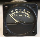
This is the meter that I have. It has a nice AC scale on it, but obviously, runs on very low levels of DC voltage, this I need a simple circuit to make this read (semi) accurate AC voltages.
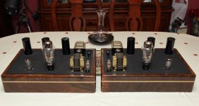
My plan is to use it on the face of a small box that will have a bucking transformer for a pair of tube amps I've built. The tube amp power transformer is wound for 115vAC primary whereas my household mains provide 122-125vAC mains. Thus, the power transformers are running a bit hot (75c - and it still pretty cool here in Pennsylvania) and I'd like to reduce the voltage and the heat so they don't burn up. The meter is just a "because I can" type of thing to go on the front of the box that will hold my bucking transformer.
Really don't much care if I implement this for peak vs rms voltage. I just want to develop a circuit that will make this meter read the mains voltages after my bucking transformer is in place. Rod's circuit seems to be what I am looking for, but obviously takes a DC input. I was just going to rectify my AC mains, and subtract off ~140v with a pair of zener diodes, and run the rest into the circuit.
Should I be aiming for something different?
Attachments
If your transformers are getting hot, you want to base your measurement on average: average voltage will dictate the magnetising current, and thus the saturation threshold.
An average detector is no more complex than a peak one.
When I have some time, I will sketch a simple circuit
An average detector is no more complex than a peak one.
When I have some time, I will sketch a simple circuit
Pass DIY Addict
Joined 2000
Paid Member
Here is a possible example, among many others.
In the simulation, the input voltage is stepped between 100, 115 and 130V.
You can see that the output current varies between practically zero (heavily pulsed, but the average value is negligible) and 400µA (FSD).
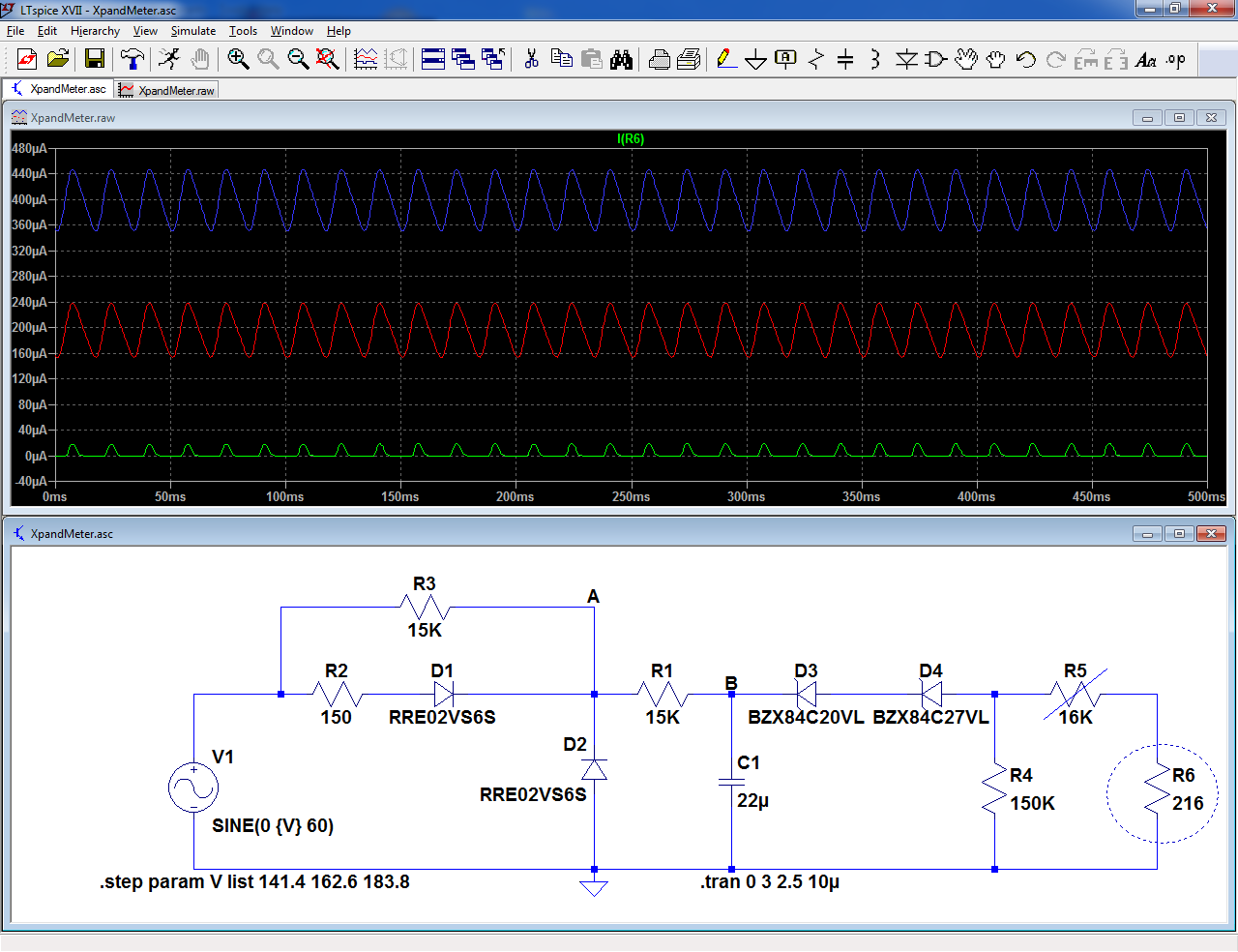
The diodes/resistors arrangement ensures that the voltage at the node A reflects the halfwave average value of the incoming waveform:
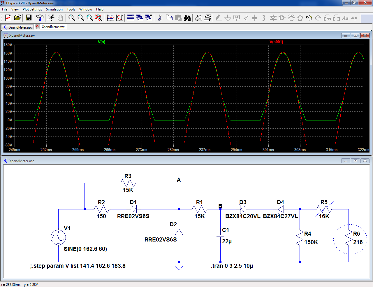
This sim shows the node A against the mains waveform.
You can see parasitic "skirts" on the green waveform, but their effect on the output is small, and anyway the size of the skirts depends on the filter cap voltage, which itself reflects the average value.
The effect is thus minimal.
It would be possible to eliminate them completely by making R3 smaller, but this would increase the dissipation over 500mW. Currently, a 1W resistor is sufficient.
Neglecting the output current, the voltage on the node B is the average value of the halfwave waveform for 115V: 115*√2/Π=51.77V:
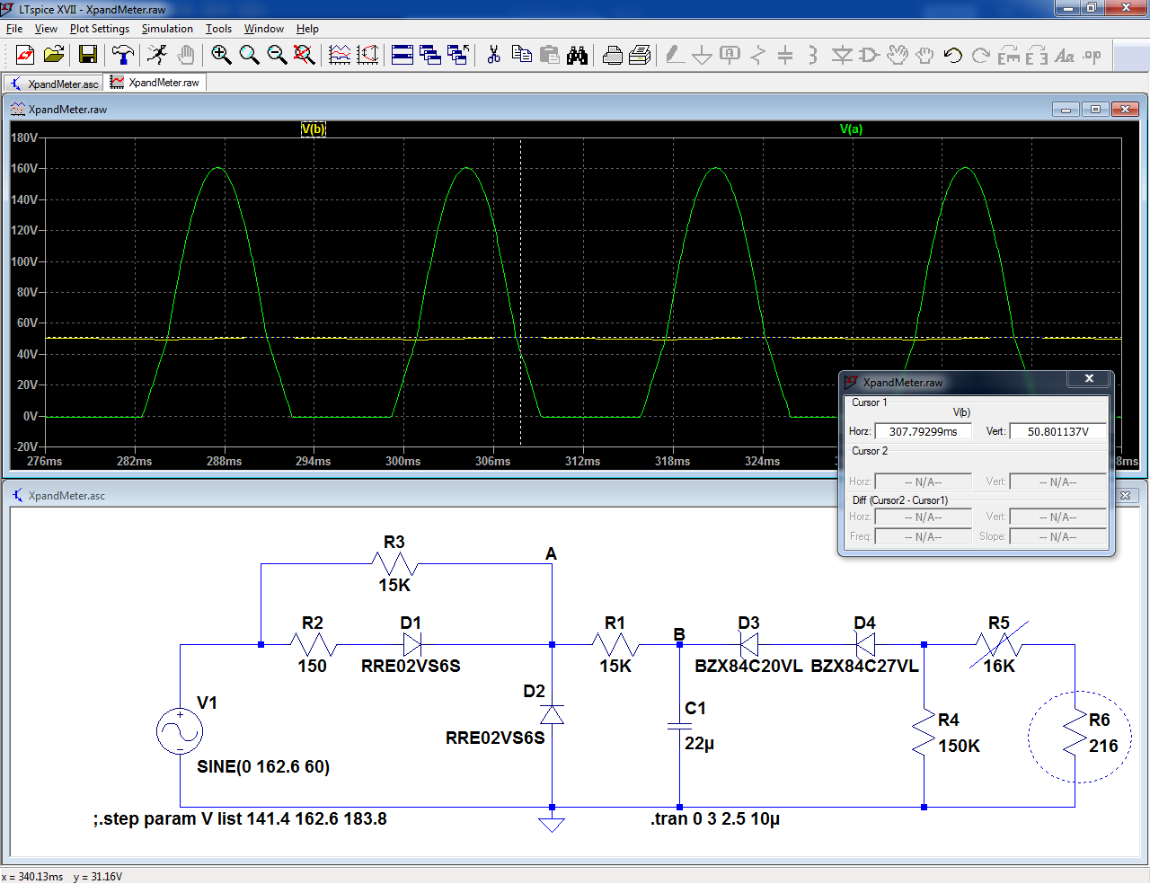
You have to use a zener having a knee voltage in this region. I opted for a total of 47V in the sim, but depending on the actual components used, your mileage may vary. You can use R5 for the final calibration.
R2 is not strictly required, but it protects the diodes against incoming spikes.
The diodes can be any HV (>600V) type
In the simulation, the input voltage is stepped between 100, 115 and 130V.
You can see that the output current varies between practically zero (heavily pulsed, but the average value is negligible) and 400µA (FSD).
The diodes/resistors arrangement ensures that the voltage at the node A reflects the halfwave average value of the incoming waveform:
This sim shows the node A against the mains waveform.
You can see parasitic "skirts" on the green waveform, but their effect on the output is small, and anyway the size of the skirts depends on the filter cap voltage, which itself reflects the average value.
The effect is thus minimal.
It would be possible to eliminate them completely by making R3 smaller, but this would increase the dissipation over 500mW. Currently, a 1W resistor is sufficient.
Neglecting the output current, the voltage on the node B is the average value of the halfwave waveform for 115V: 115*√2/Π=51.77V:
You have to use a zener having a knee voltage in this region. I opted for a total of 47V in the sim, but depending on the actual components used, your mileage may vary. You can use R5 for the final calibration.
R2 is not strictly required, but it protects the diodes against incoming spikes.
The diodes can be any HV (>600V) type
Attachments
Pass DIY Addict
Joined 2000
Paid Member
Pass DIY Addict
Joined 2000
Paid Member
Since I have no experience with spice, I have a question about this circuit that you so kindly developed.
The diodes you specified are 250mW surface-mount variety. While these are readily available from Mouser, I'm not confident that I will be able to reliably solder to these tiny devices without cooking them. Can I substitute 1w 20v and 27v through-hole zeners (such as 1N4747A and 1N4750A), or do I need to stick with the 250mW variety? I could always order plenty of extras in the event that I cook them with my iron...
The diodes you specified are 250mW surface-mount variety. While these are readily available from Mouser, I'm not confident that I will be able to reliably solder to these tiny devices without cooking them. Can I substitute 1w 20v and 27v through-hole zeners (such as 1N4747A and 1N4750A), or do I need to stick with the 250mW variety? I could always order plenty of extras in the event that I cook them with my iron...
Last edited:
No need to worry: all the components are generic, and you can use your favorite 0.4 ~0.5W TTH type.
If you use larger types, like 1.3W, you may need to use a slightly higher voltage.
You can tweak the exact voltage by adding diodes or LEDs in series.
R3 is the only resistor that needs a 1W rating. The diodes can be 1N4007.
C1 needs a 63V or larger rating.
If you use larger types, like 1.3W, you may need to use a slightly higher voltage.
You can tweak the exact voltage by adding diodes or LEDs in series.
R3 is the only resistor that needs a 1W rating. The diodes can be 1N4007.
C1 needs a 63V or larger rating.
Pass DIY Addict
Joined 2000
Paid Member
Pass DIY Addict
Joined 2000
Paid Member
Elvee - thanks again for your time to provide this circuit. I finally had some time to build it. The nice part is that I had everything I needed in my parts box (it's about time!). I used three zener diodes in series: 20+20+12, and two 47uF caps in series that measure 23uF. Diodes are 1n4007. I had exact values for everything else.
I have a question about the behavior of the meter. I adjusted the pot to calibrate the analog meter to my DMM at 115vAC. Then, I used my variac to see how it reads at other AC voltages. What I'm finding is that the analog meter reads "extra" low below the calibration point and "extra" high above this same calibration point. I also measured the voltage across the three zener diodes at each AC voltage input level. Here are some measurements, the center column is the analog meter:
DMM..........Meter.......V across zeners
105vAC.......101v.........49.2v
110vAC.......106.5v.......49.9v
115vAC.......115...........50.1v
120vAC.......123.5v.......50.1v
The amount of voltage "error" is symmetric around the calibration point of 115vAC. Is it possible to adjust the zener diode value or one of the resistors to reduce the amount of error? Or is this just the accuracy limit of this type of meter/circuit?
Thanks!
Pass DIY Addict
Joined 2000
Paid Member
Ooops, looking again at the schematic, I see that you have 20v + 27v zeners  . I was reading the text and aimed at 52v (average value of the halfwave waveform) instead of 47... This explains why my zeners are showing rising voltage at the low end of the scale and likely accounts for the additional voltage drop. This is an easy swap to make, I'm sure I have some 6.8v zeners in my box.
Like most things in life, this looks like another case of "operator error."
. I was reading the text and aimed at 52v (average value of the halfwave waveform) instead of 47... This explains why my zeners are showing rising voltage at the low end of the scale and likely accounts for the additional voltage drop. This is an easy swap to make, I'm sure I have some 6.8v zeners in my box.Like most things in life, this looks like another case of "operator error."
Pass DIY Addict
Joined 2000
Paid Member
Do you have any transistors? The Base-Emitter junction is usually "same as" a 7V (more or less; often 6.8V) Zener.
Zener diode - Wikipedia
Which pin is which?? Put it in any old way. Possibilities are 0.7V, 7V, and 40V. If you find 0.7V, turn it around. If you find 40-some V, swap E and C legs.
Obviously a BJT is not specified for Zener use. Mostly you can't pick your voltage. And a few odd devices have other breakdowns. But stuff from the last 45+ years will mostly be 7V Bv(B-E).
Pass DIY Addict
Joined 2000
Paid Member
Ahhh - now I see. Thank you for the additional details! I hadn't considered this as an option. As I don't have many (any?) spare generic transistors in my box, I'll use a zener for now. Thanks for providing an alternative solution!
I'm hoping to find time to make the substitution tonight.
I'm hoping to find time to make the substitution tonight.
Pass DIY Addict
Joined 2000
Paid Member
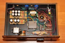
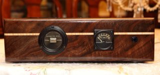
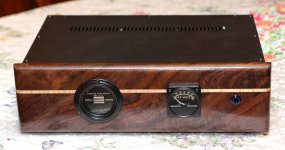
After a bit of work, here is the final product. I built one box that has the outboard supply for my turntable, Pearl II phono stage, and a step down bucking transformer to provide 115vAC to my 300B amps. The box matches my tube amps.
Thanks again for the help with the circuit for the meter, Elvee. It works great! I found a nice vintage hours meter to keep track of tube life, but it makes a bit more mechanical noise that I'd like. I might switch it out for a digital meter that fits in the same hole.
Thanks again for the help with the circuit for the meter, Elvee. It works great! I found a nice vintage hours meter to keep track of tube life, but it makes a bit more mechanical noise that I'd like. I might switch it out for a digital meter that fits in the same hole.
Attachments
- Home
- Design & Build
- Parts
- Need help with an Expanded Scale Meter