Hi Guys.
I'm looking at freshening up the crossovers in a pair of NS 670 Loudspeakers.
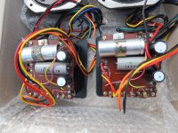
Each crossover includes: 2 upright electrolytic cans. One is marked 18µF(M) 50V CE P, the other is marked 47µF(M) 50V CE P
Two cylindrical cans lying down: One is marked 3.5µF(M) 100 WV MPM AC, the other is marked 2.7 M 160V
The one marked 2.7 M, I'm not sure of.
Are they all µF values?
The 47µF poly's I have on hand is much bigger than the old electrolytic ones and connect at each end rather than at the base on the existing upright style.
Would you recommend fitting them to a secondary outboard circuit board via wiring?
Is this recap exercise worthwhile?
cheers Cliff
I'm looking at freshening up the crossovers in a pair of NS 670 Loudspeakers.
Each crossover includes: 2 upright electrolytic cans. One is marked 18µF(M) 50V CE P, the other is marked 47µF(M) 50V CE P
Two cylindrical cans lying down: One is marked 3.5µF(M) 100 WV MPM AC, the other is marked 2.7 M 160V
The one marked 2.7 M, I'm not sure of.
Are they all µF values?
The 47µF poly's I have on hand is much bigger than the old electrolytic ones and connect at each end rather than at the base on the existing upright style.
Would you recommend fitting them to a secondary outboard circuit board via wiring?
Is this recap exercise worthwhile?
cheers Cliff
Last edited:
Yamaha NS-670
To aid the identification of components, photographs are most useful (see attachment).
I presume the puzzling cap is 2.7uF - to be absolutely sure, you would have to measure it on the capacitance scale on your multimeter, or use your ESR meter.
diymore LCR-T4 ESR Meter Transistor Tester Diode Triode Capacitance SCR Inductance Mega328 MOS PNP NPN With Test Hooks (Battery buckle with Case): Amazon.co.uk: Business, Industry & Science
Yes, it's OK to be creative when substituting different size/orientation capacitors - they may be mounted 'off-board' in the way you suggest.
The recap exercise is only really necessary if the original caps are out of spec (high capacitance/ESR). Again, measurement is your friend.
Replacing the capacitors with different types may alter the balance of the crossover network as Yamaha intented it to be, and alter the sound of the speaker - different capacitors are not necessarily better capacitors!")
To aid the identification of components, photographs are most useful (see attachment).
I presume the puzzling cap is 2.7uF - to be absolutely sure, you would have to measure it on the capacitance scale on your multimeter, or use your ESR meter.
diymore LCR-T4 ESR Meter Transistor Tester Diode Triode Capacitance SCR Inductance Mega328 MOS PNP NPN With Test Hooks (Battery buckle with Case): Amazon.co.uk: Business, Industry & Science
Yes, it's OK to be creative when substituting different size/orientation capacitors - they may be mounted 'off-board' in the way you suggest.
The recap exercise is only really necessary if the original caps are out of spec (high capacitance/ESR). Again, measurement is your friend.
Replacing the capacitors with different types may alter the balance of the crossover network as Yamaha intented it to be, and alter the sound of the speaker - different capacitors are not necessarily better capacitors!
Attachments
There are nice photos of the crossover components in this link: Yamaha NS670 Re-cap? - Speakerplans.com Forums
Yamaha NS-670
To aid the identification of components, photographs are most useful (see attachment).
I presume the puzzling cap is 2.7uF - to be absolutely sure, you would have to measure it on the capacitance scale on your multimeter, or use your ESR meter.
diymore LCR-T4 ESR Meter Transistor Tester Diode Triode Capacitance SCR Inductance Mega328 MOS PNP NPN With Test Hooks (Battery buckle with Case): Amazon.co.uk: Business, Industry & Science
Yes, it's OK to be creative when substituting different size/orientation capacitors - they may be mounted 'off-board' in the way you suggest.
The recap exercise is only really necessary if the original caps are out of spec (high capacitance/ESR). Again, measurement is your friend.
Replacing the capacitors with different types may alter the balance of the crossover network as Yamaha intented it to be, and alter the sound of the speaker - different capacitors are not necessarily better capacitors!
Thanks Galu.
Can I leave the caps in their soldered circuit board when testing?
The diy meter is well priced.
Does it have probes with the kit?
Also, a thought. If I run wires from the existing vacated termination points on the circuit board to the new circuit board containing the upgraded cap, what's the best way to fix them.
If I solder the bared section directly to the holes on the old board won't this be a weak point where the wire can flex?
Is it better to solder male terminals onto which I can affix the spade terminated cables?
Cliff
Cliff
Last edited:
Hi Cliff!
Before we continue, please allow me to give you some tips on how to streamline your posts.
1. The forum rules expressly ask you not quote an entire previous post, as doing so clutters up the thread. You can, however, quote any relevant part of the post by editing out unwanted content in the area between the square quote brackets.
2. Your posts have unnecessary double spacing between paragraphs. This may be because you are using Firefox as your browser, in which case there is a fix. See post #9 in this thread: Post Formatting Issues?
Cheers!
1. At least one leg of a component must be lifted from the circuit in order to make measurements on it.1. Can I leave the caps in their soldered circuit board when testing?
2. The diy meter is well priced. Does it have probes with the kit?
3. If I solder the bared section directly to the holes on the old board won't this be a weak point where the wire can flex?
2. The ESR meter has short test leads which they call 'test hooks'. A basic requirement for the speaker renovator is a multimeter which includes inductance and capacitance scales: https://www.amazon.com/Sinometer-VC...00N2LT8O8/ref=cm_cr_arp_d_product_top?ie=UTF8 The ESR meter to which I linked is a useful addition since it provides extra functions.
3. Simply prevent the wires from flexing by, for example, tying them down with plastic ties.
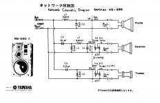
Couldn’t find the 670 ....Here’s the 690 pretty sure it’s exactly the same configuration just a couple different values....mid seems the same.
Edit...I hadn’t found this schematic when I did mine and did not realize the 18uf was a series cap for the mid......I might have used poly there if I’d known, still sounds good with the electrolytic though.
Edit...I hadn’t found this schematic when I did mine and did not realize the 18uf was a series cap for the mid......I might have used poly there if I’d known, still sounds good with the electrolytic though.
Attachments
Last edited:
OK Cliff, thanks to Bob we now know the location of the capacitors in your crossover:
The 47uF is in parallel with the woofer (the woofer "shunt").
The 18uF is in series with the midrange, and the 3.5uF is in parallel with the midrange.
The 2.7uF is in series with the tweeter.
The large value woofer cap can be an electrolytic type when a film cap of the same value would be physically too large to fit on a compact circuit board.
you would have to measure it on the capacitance scale on your multimeter, or use your ESR meter.
Thanks Galu.
I ordered the model meter you recommended.
Keen to test caps (and inductors) in future.
Last edited:
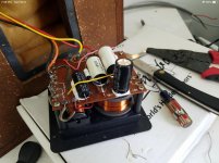
Nice job Bob.Here’s the ones I just did..
Out of interest, what's that white stuff you have the caps sitting on?
Cliff
The 47uF is in parallel with the woofer (the woofer "shunt").
The large value woofer cap can be an electrolytic type.
Might need a hand working through the schematic.
First time I've come across parallel vs series when connecting caps to Drivers??
If I stick to the same circuit boards caps termination points (as long as its all original) would the parallel and series issues automatically be taken care of?
Also I have two spare 47uF film caps left over from the Technics job.
Is it still worth using them?
Total originality isn't as much of an issue for the NS670'S.
Here I'm going for sound.
Bob did say he was pleased with the enhanced sound he experienced.
Maybe it could have gone up another level if the electrolytics had been all replaced?
Last edited:
1. In a basic LC filter circuit, the low frequency voltages appear across the capacitor (C) while the high frequency voltages appear across the inductor (L).1. First time I've come across parallel vs series when connecting caps to Drivers??
2. If I stick to the same circuit boards caps termination points would the parallel and series issues automatically be taken care of?
3. Also I have two spare 47uF film caps left over from the Technics job. Is it still worth using them?
Therefore the woofer is connected in parallel with the capacitor in its section of the crossover, while the tweeter is connected in parallel with the inductor (leaving the capacitor in series) in its section of the crossover.
Look at Section 91 of this site Basic Car Audio Electronics for some basic information on how crossovers work. Stop reading when you get to the part on "Comparing Different Filter Types" as that knowledge is not required in this renovation.
2. Yes - you would not be changing the position of the capacitors in the circuit.
3. Yes - since you have them, you might as well use them.
- Status
- This old topic is closed. If you want to reopen this topic, contact a moderator using the "Report Post" button.
- Home
- Design & Build
- Parts
- Capacitors for NS 670 Louspeakers