I am actually not in disfavor of possible variances due to types of resistors. The smaller they get, the more their tempcos will start to effect their actual resistance, since the voltage levels mostly stay the same in audio. The current density also can get to a point where excess noise starts to be a factor. But at those voltage swings the music should be so loud that the excess noise only a tiny speck in the mix, totally inaudible.
I do find the subject interesting tho if only to have the possible option of getting a dB or so better NF or distortion, but not so much because I think I can hear it.
We ran into this at my old job. A board used 0402 resistors and you could watch signals drift as everything heated up. Finally someone looked at the temp co rating of 0402 parts and it all made sense.
There are always applications where the right resistor matters. I was regailed with a story recently of a bulk foil required to sort out an ATE rig that was giving the wrong answers. But that was simple engineering. Likelywise the link to Susy's MELF experiments. Feedback resistors dissipate power and it's textbook stuff.
A load resistor that may only see 5-10mV across it? And whose purpose (for MC stages) is only to deal with ultrasonic ringing I have more of an issue with. For DIY 'it was only 50c' is of course a valid answer.
A load resistor that may only see 5-10mV across it? And whose purpose (for MC stages) is only to deal with ultrasonic ringing I have more of an issue with. For DIY 'it was only 50c' is of course a valid answer.
There are no sonic differences. It's audiophile mythology.
change your amps, your resistors, ... your ears ?
")
Perhaps in certain designs - like the AKSA-Lender, the type of resistor matters.
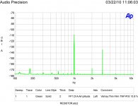
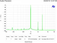
They show how the distortion spectrum changes - metal film feedback resistor
makes the 2nd harmonic less then the third.
Carbon film, as the feedback resistor, causes the 3rd harmonic to be less than the 2nd harmonic.
See the results of the measurements here.
They show how the distortion spectrum changes - metal film feedback resistor
makes the 2nd harmonic less then the third.
Carbon film, as the feedback resistor, causes the 3rd harmonic to be less than the 2nd harmonic.
See the results of the measurements here.
Why use high power handling resistors for microwatt levels?
IMHO, its the consistency. A high power resistor is less susceptible to changes and less likely to heat up.
That's basic textbook engineering again. The feedback resistor cannot be corrected by the feedback loop, and can dissipate significant power. It's possibly the most critical component to thing about.They show how the distortion spectrum changes - metal film feedback resistor
makes the 2nd harmonic less then the third.
.
IMHO, its the consistency. A high power resistor is less susceptible to changes and less likely to heat up.
with 1mV across it? I asked a specific question on a specific application.
I just asked what textbook is saying that...You didn't provide any.You just want to show off with some misterious knowledge that there isn't nowhere to be found. It's not the first time you do it either.You need to think about the problem a bit more before you make comments like that.
And i did think about that...you are completely and utterly wrong. The resistor itself is in the feedback loop . You cannot compare the distortions introduced by two different resistors in the audio band unless they are high value and one is wirewound.It's a very simple logic to back this and no phylosophical misterious concept can destroy it.
there's no filter made with just one resistor unles there's some additional capacitance or inductance around. The resistive part won't produce any distortion all by itself. Usual resistors used in feedback path ,being it carbon or metal don't have significant inductance or reactance to compound a filter in the audio band of interest.Think about what happens when the feedback loop is a filter, which it nearly always is.
Any non-linearities in the feedback network will be corrected and added to the output (which is not wanted).
Imagine a pathalogical case with an amplifier with a low open loop distortion and a poorly chosen feedback resistor that adds distortion. The action of negative feedback will add the correction signal for that resistor back into the output, increasing the overall distortion. This was shown in the link to Suzy's amplifier tests where putting a MELF in rather than a teeny thin film significantly reduced distortion.
Imagine a pathalogical case with an amplifier with a low open loop distortion and a poorly chosen feedback resistor that adds distortion. The action of negative feedback will add the correction signal for that resistor back into the output, increasing the overall distortion. This was shown in the link to Suzy's amplifier tests where putting a MELF in rather than a teeny thin film significantly reduced distortion.
well...you're talking about temperature drift when you're not choosing the right power for the resistor...milf resistors are handling temperature better at the same volume with other species, but that doesn't mean that a resistor by itself is causing any distortion when NOT poorly chosen one. A very old trick is to put a 10 times higher power resistor than needed and that's all ...
You said that the the feedback loop can't act upon the feedback resistor itself .If its value drifts away you're right, but that wouldn't be significant if the resistor's dissipation power is chosen well and again...unless you're designing some very high precision circuits i can't see why would you bother with it.
Some time ago i was testing very high precision high voltageDC power supplies(if i remember right it was somthing like 0.003 v kind of precision for 3 kWatts of power smps... )and i remember that they were using multiple smd resistors in a raw in both parts of the feedback divider to match the temperature coeficient drift .If i'm not wrong about that, Marcel VDG talked about that in other topic i think.
Some time ago i was testing very high precision high voltageDC power supplies(if i remember right it was somthing like 0.003 v kind of precision for 3 kWatts of power smps... )and i remember that they were using multiple smd resistors in a raw in both parts of the feedback divider to match the temperature coeficient drift .If i'm not wrong about that, Marcel VDG talked about that in other topic i think.
Last edited:
No Bill,
Resistor distortion is just starting to appear in textbooks. You know where the current measurements bit started 10 years ago, but seem to have forgotten the important results.
Low temperature coefficient is nice as that reduces odd order harmonic distortion. Even order distortion is a sign of very bad resistors. So of course some folks prefer that sound, as even order distortion masks other bits of bad stuff. Also adds a musical richness to sounds, although that is in the end coloration. As to the artistic effect of distortion ask any fan of Pablo Picasso!
Now using a resistor at a fraction of the power rating reduces distortion, by reducing temperature rise. In some resistor types it also lowers noise. However noise is not as large a concern in properly designed equipment. The major exception is the input stages of low level preamps, such as phonograph preamplifiers.
When using surface mounted resistors I prefer the metal film types in the 1208 size. I very particularly do this in my now thousands of microphone preamplifiers. The microphones came out on top of a listen-off of the other microphones intended for security use in prisons! (Who knew audiophile concerns also affected other folks with a much more serious attitude.)
For thumbnail ID just mouse over the image. For those who haven't seen these measurements before, the test excitation is 1,000 hertz at a level of 0 dB reference and suppressed by the measurement technique. 1,000 ohm resistors shown are tested at a small fraction of rated power.
Attachments

Last edited:
Bill,
Then I must assume your diet really has affected your memory! Using a string of the same resistors to match and remove resistor distortion from feedback loops is much older. Accurately measuring distortion is what was shown and that method now widely copied is at ten years.
ES
Then I must assume your diet really has affected your memory!
Using a string of the same resistors to match and remove resistor distortion from feedback loops is much older. Accurately measuring distortion is what was shown and that method now widely copied is at ten years.ES
- Status
- This old topic is closed. If you want to reopen this topic, contact a moderator using the "Report Post" button.
- Home
- Design & Build
- Parts
- What are the sonic differences between various type of SMD resistors??