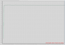
Here's one that needs less than 0.2V headroom. Measured data on a real CCS taken with a real curve tracer, see Figure 2 below.
I used a circuit taken from a website linked here on diyAudio -- post #10. Just a couple of quick tweeks and: Bob's your uncle.
_
I used a circuit taken from a website linked here on diyAudio -- post #10. Just a couple of quick tweeks and: Bob's your uncle.
_
Attachments
No doubt this is a good circuit.
Way too much sophisticated for ma application, where I do not need high accuracy neither very low drop.
What I need is a current that doesn't go lower than 4mA and higher than 8mA over a voltage range 1.5V 20V.
With one BJT it can marginally be done.
With two BJTs I can make a near perfect 4mA CCS easy to adjust at other values.
are you unable to tune your "near perfect 4mA CCS" to meet your spec of (4ma < Iout < 8ma) with (1.5V < Vout < 20V)?
or is it quite possible to make a tuning that achieves those specifications, but the circuit costs too much?
_
or is it quite possible to make a tuning that achieves those specifications, but the circuit costs too much?
_
Attachments

here's a couple ideas for you....I am guessing you want a current source driven from the battery towards ground?
1. use 1 PNP, 2 diodes and 2 resistors. If the the Vce_sat is 0.1V (approx) you can get the current source to run to within 0.1 Volt of the rail.
Circuit looks something like this (if my cheezy diagram comes out okay)
VCC VCC
| |
Diode R2
| /
Diode |/
|-_______| Q1 (PNP)
| |\
| \
R1 Iout
|
|
GND
Iout = Vdiode/R2
Your spec was 5 mA. R2 ~ 0.7V/5mA =140 Ohm.
The maximum load it can drive is roughly (Vbat_min - Vce_sat) / Iout
(1.5V - 0.1V) / 5mA = 280 Ohm.
You can make this think more precise if you want by using matched parts.
2. The other idea I had involves TLV431 which can run to 1.25V. You'd need some current mirrors, I think but it's not so messy.
Simple solution is #1.
Hope this is helpful.

While BF862 is out of current production, perhaps CPH5910? https://www.onsemi.com/pub/Collateral/ENA1965-D.PDF
The LND150 might be marginal for 5mA, esp at low voltage. A BSS126 (Infineon) might be a better choice, but I doubt it would work with 1.5V headroom. If you don't care that much about ultimate accuracy, a 2N3906/2N3906 and 3 resistors could make the grade.
LND150 won't do. Idss = 2.5 mA, and it is nicely consistent.
Here are 7 samples:
< Microchip_LND150 | Gerhard Hoffmann | Flickr >
To the left/right, there are some other transistor types. The axis is easier to read
if you download the pics in original size.
Cheers, Gerhard
I will implement a 4mA CCS using 2 Bjts and and 2 resistors.
Current Sources, Sinks and Mirrors in Audio
Fig 5.1 schematic B
Simple, bullet proof.
This gives better than 5 Megohm dynamic impedance.
I do not need that much, simulation shows better than my expectations with a 200K current source.
Current value is easy to adjust by changing the emitter resistor.
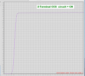
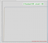
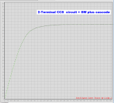
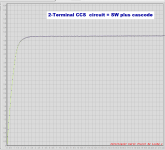
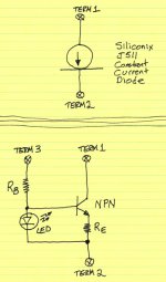
I fooled around in the workshop for a half hour this morning, measuring what National Semiconductor calls "True Two-Terminal Current Source Circuits". These are circuits which float with respect to the supply rails, and which make exactly two connections to the external world. My hand-drawn Figure 1 illustrates:
On top is a Siliconix "J511" current regulator diode. It has exactly two terminals, Term1 and Term2. These can be connected to the top rail, or to the bottom rail, or indeed to any two circuit nodes, whether they be rails or not. I wish I had a J511 to measure but, alas, I do not.
On bottom is a current source circuit having three terminals. It's a current source between Term1 and Term2, and then you must attach Term3 to a DC voltage to provide correct biasing -- usually the top rail.
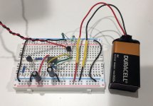
This morning's measurements were made ONLY on circuits like the top one, having two and only two terminals connected to the outside world.
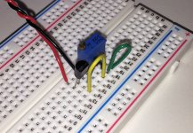
I tried two basic constant current source circuits: (1) the Scott Wurcer circuit, as described in this thread; (2) the Carl Nelson circuit, which he designed for National Semiconductor. Each of these CCS circuits has exactly two electronic components: a resistor and a gain element housed in a TO-92 package. To speed up the measurement work this morning, I used a multiturn trimmer potentiometer as the resistor. This makes it very quick to dial in the exact current I wanted. The trimmer is the rectangular blue object in the photo of Figure 2.
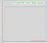
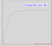
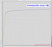
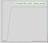
I measured each of the basic CCS circuits (a) without; and also (b) with; a cascode. This flattens the I-versus-V curve, but pushes the "knee" to the right. This is the point where the CCS starts becoming a good current source with approximately constant current.
Measurement results are shown below. I made a "zoom in" plot near the knee, and a "zoom out" plot showing the entire >20V range of operation, for each circuit. Thus there are eight plots total.
Some of them are quite pleasant. Click on the white "X" at the lower left corner of each image, to see it full size and undistorted.
_
On top is a Siliconix "J511" current regulator diode. It has exactly two terminals, Term1 and Term2. These can be connected to the top rail, or to the bottom rail, or indeed to any two circuit nodes, whether they be rails or not. I wish I had a J511 to measure but, alas, I do not.
On bottom is a current source circuit having three terminals. It's a current source between Term1 and Term2, and then you must attach Term3 to a DC voltage to provide correct biasing -- usually the top rail.
This morning's measurements were made ONLY on circuits like the top one, having two and only two terminals connected to the outside world.
I tried two basic constant current source circuits: (1) the Scott Wurcer circuit, as described in this thread; (2) the Carl Nelson circuit, which he designed for National Semiconductor. Each of these CCS circuits has exactly two electronic components: a resistor and a gain element housed in a TO-92 package. To speed up the measurement work this morning, I used a multiturn trimmer potentiometer as the resistor. This makes it very quick to dial in the exact current I wanted. The trimmer is the rectangular blue object in the photo of Figure 2.
I measured each of the basic CCS circuits (a) without; and also (b) with; a cascode. This flattens the I-versus-V curve, but pushes the "knee" to the right. This is the point where the CCS starts becoming a good current source with approximately constant current.
Measurement results are shown below. I made a "zoom in" plot near the knee, and a "zoom out" plot showing the entire >20V range of operation, for each circuit. Thus there are eight plots total.
- (2 circuit types) x (2 cascoding options (Yes/No)) x (2 plot magnifications)
Some of them are quite pleasant. Click on the white "X" at the lower left corner of each image, to see it full size and undistorted.
_
Attachments
-
 Cascoded_Carl_Nelson_full_range.PNG32.8 KB · Views: 105
 -
 Carl_Nelson_zoom_in.PNG31.1 KB · Views: 102
 -
 Carl_Nelson_full_range.PNG32.5 KB · Views: 108
 -
 Cascoded_Scott_Wurcer_zoomed_in.PNG31.7 KB · Views: 113
 -
 Cascoded_Scott_Wurcer_full_range.PNG32.2 KB · Views: 187
 -
 Scott_Wurcer_zoomed_in.PNG32.7 KB · Views: 185
 -
 Scott_Wurcer_full_range.PNG37.9 KB · Views: 195
 -
 CCS_two_components.JPG228.2 KB · Views: 203
 -
 schematic.jpg236.6 KB · Views: 226
 -
 Cascoded_Carl_Nelson_zoom_in.PNG33.5 KB · Views: 117
You can caracterize CCSs by their dynamic resistance. Infinity for an ideal CCS.
This impedance versus voltage tells it all.
Another aspect is thermal stability.
Depending of the application one can look for a 0 tempco or a known stable tempco.
There are plenty to choose from, it is fun to test them or simulate them.
This impedance versus voltage tells it all.
Another aspect is thermal stability.
Depending of the application one can look for a 0 tempco or a known stable tempco.
There are plenty to choose from, it is fun to test them or simulate them.
I fooled around in the workshop for a half hour this morning, measuring what National Semiconductor calls "True Two-Terminal Current Source Circuits". These are circuits which float with respect to the supply rails, and which make exactly two connections to the external world.
Unfortunately on an IC your can choose the Z/L of the FET to be the "zero TC"
point this does not work with using any old JFET. This idea was for a tiny circuit to light up an op-amp, you don't need a curvature corrected bandgap to light up an op-amp.
- Status
- This old topic is closed. If you want to reopen this topic, contact a moderator using the "Report Post" button.
- Home
- Design & Build
- Parts
- Low current constant current source