These papers do seem to be demonstrations of tiny parameter changes and then make a huge jump to blaming these for audible differences.
The experimental measurement methods could do with some justification too.
Headphone cables are usually copper for flexibility, so where is an inductance change coming from unless it is thermal
The experimental measurement methods could do with some justification too.
Headphone cables are usually copper for flexibility, so where is an inductance change coming from unless it is thermal
...a huge jump to blaming these for audible differences....
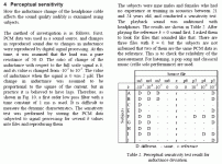
The Headphone paper has a interesting Table 2.
I have heavily edited and compressed this passage to point-out what I am critiquing; you really want to read the whole paper for context (and easier reading).
He digitally modified music files with the effect he proposes, in degrees from 1ppm to 1,000ppm. He asked 9 young people to listen to the raw track, then find other tracks which "sound different". His Table 2 says that nearly all subjects could hear 1,000ppm (m3/p3), some heard 100ppm or less, none heard 1ppm. And oddly, none heard difference for the identical file.
Attachments
The leading edge of a fast slew will skin the current, so the inductance during slew will be reduced a maximum of 15 nH per foot per conductor. When the slew is over, the current will redistribute to uniform cross section and the wire during that time will store inductive energy from the signal current.If I read it correct, the inductance variation in the headphone cable due to the current is about 0.5nH. A tall order to translate that in audible differences.
Jan
.5 nH is trivial in that context.
Measurement of a twisted pair induces that as well as proximity. As the current redistributes after a slew, many meters can misinterpret the additional system energy storage as capacitive effects.
Twisted pair in open air also has capacitive coupling based settling after a slew. The understanding of all the actual effects, how they confound the measurements, and the resulting conclusions...sigh.
None of this is really of use, the paper authors need to revisit the blackboard..
Jn
Last edited:
This is a linear effect and gives a frequency sensitivity. The page extract aboveThe leading edge of a fast slew will skin the current, so the inductance during slew will be reduced a maximum of 15 nH per foot per conductor. When the slew is over, the current will redistribute to uniform cross section and the wire during that time will store inductive energy from the signal current.
...
Jn
describes an effect depending on the square of the current, is non-linear. Where that comes from is not explained so far in this thread
If susch an effect is real and prumably causes a second harmonic, I find it hard to believe that any listeners could hear 0.01% 2nd.
Second harmonic has to be well above 1% to be obvious
Last edited:
When an effect is dependent on both level of current and it's derivative, and the mechanism is storage (LI^2 or CV^2), most people have no idea how finicky the measurement technique becomes.This is a linear effect and gives a frequency sensitivity. The page extract above
describes an effect depending on the square of the current, is non-linear. Where that comes from is not explained so far in this thread
If susch an effect is real and prumably causes a second harmonic, I find it hard to believe that any listeners could hear 0.01% 2nd.
Second harmonic has to be well above 1% to be obvious
I pointed out how slew dependent inductance of a wire pair (which was not considered) exceeds the "odd" result mentioned by a factor of 60.
So, nah, nothing odd in the tests, just the understanding, methodology, and conclusions.
It is very difficult to explain someone's test and theory error long after the fact. I would have to be there examining the setup, using methods to check the test results.
I do applaud the effort however.
As a fun note...I am currently in the process of building a metal detector, the goal is to find an aluminum plane buried under 65 feet of sediment, with 70 feet of seawater above that.
It involves a 20 foot diameter coaxial cable search coil, a tigersaurus 250, and a spectrum analyzer to spot third harmonic eddy current dissipation..
It is scary what one gets involved with friends during a lockdown...I chose a sine excitation for the search coil, as I worry that microsecond tens of amps pulses applied to a 20 foot coil might involve some explanations to homeland security...we already warned the harbormaster...
Jn
Last edited:
Maybe my mentioned observations in post #33+37 underFound an Engineering Brief from the last (virtual) AES convention in Vienna. The author posits that interlink capacitance is modulated by the signal level. Since that capacitance forms a low pass with the load impedance, a varying capacitance has an impact on the reproduction. He states that this is a possible source of 'cable sound'.
Jan
https://www.diyaudio.com/community/threads/diy-shielded-signal-cables.368889/page-2#post-7011147
based on this effect.
- Home
- Design & Build
- Parts
- Signal-dependent cable capacitance change
