Constructed an electrical first order high pass filter on both a midrange and tweeter. The two components used were a series capacitor to resistor. The electrodynamic drivers in this study are balanced armatures.
I cannot figure out what the inherent difference is between the two capacitors used (SMD vs. Thru-hole).
SMD capacitor example
TAJB226K010RNJ AVX Corporation | Capacitors | DigiKey
Thru-hole capacitor example
TAP226K016CCS AVX Corporation | Capacitors | DigiKey
The lower curve in both the frequency response measurements are from the SMD components in the crossover. Everything else remained the same. There can't possibly be inductance in the SMD parts, can there? I
Any lessons to teach this guy?
MIDRANGE

TWEETER

I cannot figure out what the inherent difference is between the two capacitors used (SMD vs. Thru-hole).
SMD capacitor example
TAJB226K010RNJ AVX Corporation | Capacitors | DigiKey
Thru-hole capacitor example
TAP226K016CCS AVX Corporation | Capacitors | DigiKey
The lower curve in both the frequency response measurements are from the SMD components in the crossover. Everything else remained the same. There can't possibly be inductance in the SMD parts, can there? I
Any lessons to teach this guy?
MIDRANGE
TWEETER
Hi rayma,
That, is an understatement!
Hi tf1216,
You're not really going to build the crossover with surface mount parts are you??? Also, even the non-polarized high K ceramic capacitors have very high distortion. You are pretty much stuck with full size, through hole parts for the capacitors.
-Chris
That, is an understatement!
Hi tf1216,
You're not really going to build the crossover with surface mount parts are you??? Also, even the non-polarized high K ceramic capacitors have very high distortion. You are pretty much stuck with full size, through hole parts for the capacitors.
-Chris
That, is an understatement!
You could put them in anti-series if used with a flea power amp, but cheap tants have high ESR too.
Maybe that's what he's measuring. Never have heard of anyone trying this before, may never again.
Hi rayma,
That is true, and pointless as you alluded to.
-Chris
That is true, and pointless as you alluded to.
Yes, same here.Never have heard of anyone trying this before, may never again.
-Chris
That is true, and pointless as you alluded to.
My last direct encounter (by choice) with tants was a number of years ago in some million dollar lab hardware.
There were a half dozen identical modules inside, and ALL the tants in them burst into flame and burned up
the boards, within a few days of each other. Talk about manufacturing consistency, that was impressive.
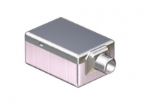
Designing an earphone that uses balanced armatures like you see from the likes of Knowles and Sonion.
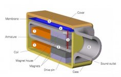
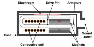
What is Balanced Armature
The midrange crossover is a 10uF capacitor and a 7.5R resistor.
The tweeter uses a 1.5uF capacitor and a 5R resistor.
The goal was to breadboard a 4-way design using thru-hole parts then mirror the design with SMD parts. The lows and lower mids compared favorably.
To complete the design SMD parts are required. Are there more preferable makeups out there?
Cross over filters will suffer from the very high distortion on electrolytics, since the signal voltages across capacitors are high in filter circuits (unlike DC-blocking caps). Tantalum is a very real fire risk and should be ruled out on that basis alone - over voltage will make them incendiary devices.
10uF as a film-cap is alas a big big and expensive, but definitely available and performant.
10uF as a film-cap is alas a big big and expensive, but definitely available and performant.
If you want to use these tant parts, connect two (of twice the value needed) in series,
with the positive terminals connected together, to make a single bipolar capacitor.
Throw away the ones that were used singly, since they have been damaged.
The current rating (as well as the voltage rating) of these parts is likely to be too low
for a passive crossover, and they will probably degrade with use.
Bipolar electrolytic types will work better than tants for this application. Use 50V rating, or higher.
SMT electrolytics have much lower current ratings than standard radial electrolytics.
Film types are best, though much larger, but the inside of a speaker is a big place.
Last edited:
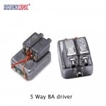
The parts are used for in-ear monitors like you would buy from a store or see on-stage at a concert. Very low voltage levels are used. The amplifier's output is set at 150mV.
I have used various types of SMD capacitors in the past and never saw any noticeable difference in the frequency response when connected in series with a balanced armature.
An in-depth study was done using multiple 1uF capacitors from tantalum to film at various voltage ratings.
It wasn't until I compared thru-hole components to the SMD ones that there is something happening above 400Hz I can't quite figure out.
It wasn't until I compared thru-hole components to the SMD ones that there is something
happening above 400Hz I can't quite figure out.
Try again with the capacitors connected as bipolar (two in series with the positive terminals connected together).
A single polarized capacitor cannot work properly in this case, so any measurements will be invalid.
The use of balanced headphones should not make any difference in the measurements.
Last edited:
")
Attachments
That makes no difference either, since a speaker system is a two terminal network.
The only thing that matters is the voltage difference between the two terminals.
Make sure that the amplifier can work with the your headphones. A balanced amplifier
requires twice the minimum impedance, compared to when it is connected as single ended.
The load impedance may be too low.
The only thing that matters is the voltage difference between the two terminals.
Make sure that the amplifier can work with the your headphones. A balanced amplifier
requires twice the minimum impedance, compared to when it is connected as single ended.
The load impedance may be too low.
Last edited:
Balanced ARMATURE drivers. Not balanced headphones. Not balanced amplifier.
A BA driver is highly efficient but narrow-band audio transducer. They were known in the 1920s for radio speakers, and 1950-2020 for hearing aids and now musicians' in-ear monitors. The typical drive voltage is under 1V. (Hearing aids work on a 1.4V cell.) While some tiny caps have bad voltage curves, probably not what is happening here.
No schematic. All we can do is flail at it. Let him clarify what he is trying to do.
Attachments
Thank you for the backup PRR. Attached is the schematic for the midrange I am working with.
There is a damper inserted into a tube that is glued to the spout of the balanced armature.
The schematic for the tweeter is very similar. The capacitor is 1uF and the resistor is 5 ohms.

There is a damper inserted into a tube that is glued to the spout of the balanced armature.
The schematic for the tweeter is very similar. The capacitor is 1uF and the resistor is 5 ohms.
Last edited:
With the hi-K ceramics they have a major voltage coefficient. The same as the source for the distortion. What it would mean is that the response of the system will change with frequency. These parts are common in the IEM's and sometimes quite a few are in there if there are a lot of drivers. You can get 1 uF COG SMT caps and they would be your best option. You may be able to get a 1 uF SMT mylar film that would fit. However the mylar is not as good as COG ceramic. Here is an example: 1825E105K500PHT Knowles Novacap | Mouser Its from knowles who are known for balanced armature drivers, not caps. And its quite pricey. I guess they want in on the headphone goldmine. I'm sure there are others but the Kemet is huge and $68 so its a non-starter.
- Status
- This old topic is closed. If you want to reopen this topic, contact a moderator using the "Report Post" button.
- Home
- Design & Build
- Parts
- Help explaining SMD Vs. Thru-hole measurements