Hi.
I'm working on a pair of Mordaunt Short Loudspeakers and need to understand the electronics involved.
In terms of crossover restoration one option it to replace like for like.
If someone has transposed the Speaker wire terminations this could be affecting the sound?
My question is:
Are Loudspeaker Driver terminals universal in terms of the current flow or are they +ve and -ve and need to be terminated correctly?
The Tweeter (marked Made in W Germany 058 8 Ohm 95-6464) has terminals marked + and -
The Woofers (MSB C No 029960) don't have any markings identifying the polarity of terminals.
Are the Woofer terminals non polarity conscious and therefore universal in terms of their orientation with the speaker terminals?
thanks
Cliff
If the speaker is transposed, it will be out of phase and will sound odd.
All loudspeakers and tweeters are polarised. On speakers without markings, the +ve terminal is usually the right hand one when viewing the rear of the speaker and the magnet is the top of the triangle shape made between the magnet and the terminals.
All loudspeakers and tweeters are polarised. On speakers without markings, the +ve terminal is usually the right hand one when viewing the rear of the speaker and the magnet is the top of the triangle shape made between the magnet and the terminals.
If the speaker is transposed, it will be out of phase and will sound odd.
All loudspeakers and tweeters are polarised. On speakers without markings, the +ve terminal is usually the right hand one when viewing the rear of the speaker and the magnet is the top of the triangle shape made between the magnet and the terminals.
Great information Jon.
Now all I have to do is to study the crossover and make sure the polarity of the speakers line up.
Thanks
Loudspeaker phase identification is definitely most important, specially on woofers.
Your Tweeter has +/- labelling, fine.
Your woofer too, although maybe they use some other way.
Using a red paint dot near the + terminal is very popular, sometimes a more obscure way is used, here in Argentina a most popular brand used different coloured fiber "washers" on terminals, quite "hidden in plain sight" unless somebody pointed that out.
But please test them yourself, with a battery, and label them accordingly.
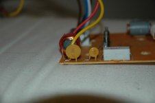
Hi Cliff! I attach a useful image of the terminals on the MSB C.
Connect a 1.5V battery across the speaker terminals so that the voltage makes the cone move outwards (not inwards). You should then mark the speaker terminal to which the positive terminal of the battery is connected as POSITIVE.
Sounds like you have a Mordaunt Short MS-25 speaker like this:
Mordaunt.Short MS-25 | Classic Hi-Fi
Attachments
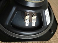
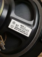
Actually, the polarity is shown on the label!
Positive is on the right which is typical, as pointed out by Jon.
Thanks G.
I never thought to equate the label with the polarity.
I think you're on the money.
")
I'll try the battery test.
Hi Cliff!
Sounds like you have a Mordaunt Short MS-25 speaker like this:
Mordaunt.Short MS-25 | Classic Hi-Fi
They're actually the MS 45Ti's.
ms45ti - Google Search
I've cleaned them up (cabinets and stands) and will have a go at refurbishing the crossovers.
They have iron speaker terminals, iron core inductors, electrolytic caps, and sandcast resistors, so I think I can achieve improvement in sound by modernising these parts.
I'll also mould some mastic on the cones to help eliminate vibration.
Thanks for your help.
Cliff
Mould mastic on the speaker basket I think you mean!
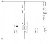
Looks like there's a couple of air core inductors in the crossover (bottom right of attached image).
The fitted inductors don't look up to much, but changing them brings up the issue of obtaining ones with the same DC resistance as the originals. I caution you that the wrong choice of iductors could make the speakers sound worse than at present.
Personally, I would settle for changing the NP electrolytic capacitors only. Bear in mind that the originals may not have deteriorated significantly so the gain in sound quality may be minimal.
P.S. I believe the 4mm speaker sockets are nickel plated brass - not iron.
Attachments
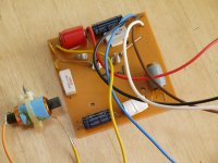
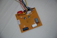
I attach the correct view of the MS45Ti crossover board. Looks like someone was trying to modify the one I attached previously.
I also attach a view of the Positec overload protection devices (the mustard colour discs, but sometimes blue). These tend to become unreliable with age and are best shorted out of circuit with a wire link. They were included because MS was keen to avoid speakers being returned due to the owner's recklessness in the application of the volume control!
I also attach a view of the Positec overload protection devices (the mustard colour discs, but sometimes blue). These tend to become unreliable with age and are best shorted out of circuit with a wire link. They were included because MS was keen to avoid speakers being returned due to the owner's recklessness in the application of the volume control!
Attachments
A fun experiment: Listen to a pair of speakers in stereo. Note how the sound SEEMS to mainly come from a point between the speakers. Now reverse the wires to JUST ONE of the speakers and listen again. You should notice the sound has an odd quality and seems to come from anywhere EXCEPT right between them.
That demonstrates out of phase speakers.
That demonstrates out of phase speakers.
I also attach a view of the Positec overload protection devices (the mustard colour discs, but sometimes blue). These tend to become unreliable with age and are best shorted out of circuit with a wire link.
Good tip G
Can I remove both "Positec overload protection devices" by cutting their wires and then restore the path by soldering the wire ends together to restore the circuit?
Thanks for the guidance.
Connect a 1.5V battery across the speaker terminals so that the voltage makes the cone move outwards (not inwards). You should then mark the speaker terminal to which the positive terminal of the battery is connected as POSITIVE.
I performed your test and identified that the right terminal is +ve.
I've removed any future doubt by marking the area near the +ve terminals with a red paint dot.
Looks like there's a couple of air core inductors in the crossover (bottom right of attached image).
The fitted inductors don't look up to much, but changing them brings up the issue of obtaining ones with the same DC resistance as the originals. I caution you that the wrong choice of inductors could make the speakers sound worse than at present.
The inductors wrapped with blue and with red are both iron core, so I'd really like to replace these.
Is there an Inductor value test I can perform with a multi meter.
Maybe this way I can replace them with parts of equal value???
Personally, I would settle for changing the NP electrolytic capacitors only. Bear in mind that the originals may not have deteriorated significantly so the gain in sound quality may be minimal.
P.S. I believe the 4mm speaker sockets are nickel plated brass - not iron.
I'll definitely replace the caps with poly film caps and cross the fingers the old ones have deteriorated to some degree.
I'll also do the magnet test on the terminals to remove any doubt regarding ferro content.
Also the resistors look pretty cheap sandcast examples.
Resistors are pretty inexpensive to buy in comparison to caps.
Is there a reason not to replace these?
Thanks
C
You need a multimeter that measures inductance (not all do). You should also measure the resistance of the inductors using the ohms scale. Look for replacements with the same inductance and similar DC resistance.Is there an Inductor value test I can perform with a multi meter.
Maybe this way I can replace them with parts of equal value???
Resistors are pretty inexpensive to buy in comparison to caps.
Is there a reason not to replace these?
In my book, resistors simply oppose the flow of current and don't make any diference to the sound. Others disagree. It's entirely up to you!
Yes, but I would solder some extra wire across the gap for good measure.Can I remove both "Positec overload protection devices" by cutting their wires and then restore the path by soldering the wire ends together to restore the circuit?
You need a multimeter that measures inductance (not all do). You should also measure the resistance of the inductors using the ohms scale. Look for replacements with the same inductance and similar DC resistance.
My Tester has an Ohms section with various values 2000k to 200.
Which range would I focus on?
It doesn't seem to have a Resistance section.
What value or symbol would I look for to measure resistance?
In my book, resistors simply oppose the flow of current and don't make any diference to the sound. Others disagree. It's entirely up to you!
I've read that quality resistors can have low inductive (less magnetic) attributes and therefore reduce interference of the sound signal.
Don't know your thoughts on the subject.
The 'Ohms section' is the resistance section, resistance being measured in ohms (Ω).
Use the lowest range as the inductors will have a very low resistance in the order of a fraction of an ohm.
I would not worry about the miniscule inductance of the present wire wound resistors in the context of your MS45Ti speakers, but there's nothing to stop you from changing themif it makes you happy.
The 'Ohms section' is the resistance section, resistance being measured in ohms (Ω).
Use the lowest range as the inductors will have a very low resistance in the order of a fraction of an ohm.
I measured the existing Inductors.
The two smaller coils which were wrapped around what looks like cardboard hollow rolls measured 1.1Ω & 1.4 Ω respectively.
The larger coils which both have solid metal cores measured 1.1Ω & 1.4 Ω respectively.
Size of the coils in this crossover didn't seem to correlate with resistance.
The tests were performed with the coils still soldered to the circuit board.
A fourth (larger coil) was housed on its own on the rear of the cabinet away from the circuit board??
I used scratched surfaces of wire nearest to the coil windings.
On one of the larger coils I had to test using the soldered points on the rear of the circuit board.
Do I replace this with air core coils of the same value?
It looks like, at a glance, inductors have more values than just Ω resistance.
There's thickness of wire in AWG & μH inductance.
How will I go about obtaining these values in the existing iron core inductors so I can replace like for like, or in other words, maintain the designed spec but eliminating the iron core element?
I would not worry about the minuscule inductance of the present wire wound resistors in the context of your MS45Ti speakers, but there's nothing to stop you from changing themif it makes you happy.
What would make me happy would be an improvement in sound performance.
I don't like spending money unnecessarily.
Then also this exercise is to expand on my practical experience.
cheers
Cliff
Last edited:
- Status
- This old topic is closed. If you want to reopen this topic, contact a moderator using the "Report Post" button.
- Home
- Design & Build
- Parts
- Loudspeaker Driver Terminals???