I have mentioned the inductor's polarity issue in other thread:
https://www.diyaudio.com/forums/parts/215751-inductor-polarity.html#post5950876
I would like to use the figures below to make it more clearly.
For the current multi-layer wire-wound coils and foil coils, they all have a spiral conducting path, their inner circles and outer circles have different diameters. And current market-available foil coils are having the most layers because each turn of these coils constructs a layer.
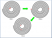
FIG.1 shows two free electrons initially placed at the center of a spiral copper wire/foil, let us assume that they are free to travel in the conductor.
FIG.2 shows the possible final positions of the two electrons, they will expel each other due to their same electric charge and finally they will stay at the two ends of the most outer turn of the spiral path, keeping themselves as far as possible from each other, i.e. they will travel from the highest potential to the lowest potential in the spiral conducting path (shorter distance to longer distance between them).
FIG.3 shows that if a voltage is applied and the two electrons in FIG.2 begin to travel to the center of the spiral with the same speed (i.e. an electron current), when they arrive the spiral center, their positions might be as shown in FIG.3, their distance between each other becomes shorter than FIG.2, i.e. the potential between them has become higher than in FIG.2, higher than where they have started.
So, I think, the electrons are easier to travel from the center to the outer turn (high to low potential), and harder to travel from the outer to the center of the spiral path (low to high potential). In other words, we need more power to "squeeze" the electrons from the outer turn to the inner turn.
Since the current flow is in the reverse direction of the electron flow, so the current must be easier to flow from the outer turn to the inner of the spiral coil. In other words, a multi-layer spiral coil could have polarities.
I have learned somewhere (in this forum?) that switching power engineers always (or prefer to) connect the outer turn of a fly-back transformer's primary coil to the positive power source to let the current in the primary coil always flow from its outer turn to the inner of the spiral coil.
If they are doing this for better efficiency, then the primary coil must be having polarities. (Maybe they have learned about this by measuring the operating temperature of the transformer?)
Anything in audio must face the final test of human ears.
Also, there are people saying that they can hear the difference when they switched the two ends of their crossover inductors. This also tells us that inductors probably have polarities.
How obvious is the polarity effect? I am not sure, but when your ears can hear the difference, then it is an issue, otherwise it's not. But considering that in an inductor it is not just two electrons flowing, it is at a grade of multiple 10^18 electrons.
Maybe I was wrong about something, if that's the case please let me know. Thanks!
https://www.diyaudio.com/forums/parts/215751-inductor-polarity.html#post5950876
I would like to use the figures below to make it more clearly.
For the current multi-layer wire-wound coils and foil coils, they all have a spiral conducting path, their inner circles and outer circles have different diameters. And current market-available foil coils are having the most layers because each turn of these coils constructs a layer.
FIG.1 shows two free electrons initially placed at the center of a spiral copper wire/foil, let us assume that they are free to travel in the conductor.
FIG.2 shows the possible final positions of the two electrons, they will expel each other due to their same electric charge and finally they will stay at the two ends of the most outer turn of the spiral path, keeping themselves as far as possible from each other, i.e. they will travel from the highest potential to the lowest potential in the spiral conducting path (shorter distance to longer distance between them).
FIG.3 shows that if a voltage is applied and the two electrons in FIG.2 begin to travel to the center of the spiral with the same speed (i.e. an electron current), when they arrive the spiral center, their positions might be as shown in FIG.3, their distance between each other becomes shorter than FIG.2, i.e. the potential between them has become higher than in FIG.2, higher than where they have started.
So, I think, the electrons are easier to travel from the center to the outer turn (high to low potential), and harder to travel from the outer to the center of the spiral path (low to high potential). In other words, we need more power to "squeeze" the electrons from the outer turn to the inner turn.
Since the current flow is in the reverse direction of the electron flow, so the current must be easier to flow from the outer turn to the inner of the spiral coil. In other words, a multi-layer spiral coil could have polarities.
I have learned somewhere (in this forum?) that switching power engineers always (or prefer to) connect the outer turn of a fly-back transformer's primary coil to the positive power source to let the current in the primary coil always flow from its outer turn to the inner of the spiral coil.
If they are doing this for better efficiency, then the primary coil must be having polarities. (Maybe they have learned about this by measuring the operating temperature of the transformer?)
Anything in audio must face the final test of human ears.
Also, there are people saying that they can hear the difference when they switched the two ends of their crossover inductors. This also tells us that inductors probably have polarities.
How obvious is the polarity effect? I am not sure, but when your ears can hear the difference, then it is an issue, otherwise it's not. But considering that in an inductor it is not just two electrons flowing, it is at a grade of multiple 10^18 electrons.
Maybe I was wrong about something, if that's the case please let me know. Thanks!
Attachments
Current is not what you have in mind.
It is not electrons travelling all the way from one end to the other.
It is a crowd pushing each others or a traffic jam moving bumper to bumper.
Each electron doesn't travel much.
YouTube
mchambin, Thanks! You are correct, drift velocity of electrons in copper is very slow, it has been bothering me of how to express the "polarity effect" in calculus form.
If we consider the motion of electrons in the spiral coil as a large group of "electron train" moving back and forth (in short range) between the outer ring and the inner, it might need to use calculus to calculate the "polarity effect" with the total moving electrons in the spiral path. And calculus is always a problem to me.
I take it as that you have agreed with me, the polarity effect is there, now it's a question of how large is it?
But as I have stated, if you can hear the difference, then it is an issue, otherwise it's not.
Maybe next time when someone feels not so good about a spiral coil, he can try to switch the polarity of the coil and see if it helps. As you know music signals are mostly polarized (non-symmetric waveform).
This is an article about asymmetric music signals.
Asymmetric musical waveforms
What is interesting is that in a single violin solo the music signals can change from positive spikes to negative spikes, which means if you have a crossover inductor with polarities, you can never get the optimized results by switching the polarity of the inductor.
I have heard some people liked the iron-core inductors more than air cores, despite the obvious hysteresis. Except hysteresis (and DCR), there is another major difference between an air core and an iron-core, i.e. the number of layers. Could it be the fewer layers of an iron-core inductor also have helped it in the preferred performance regarding polarity effect (outperformed the hysteresis distortion to some people)? If an iron-core has only one layer of winding, then it is fully symmetric and polarity free.
Anyway, a symmetric inductor without polarity seems to be the best solution for any polarized music signals.
Maybe you want to elaborate on polarized inductors? I've never seen any yet.
I was trying to give a possible explanation on how and why people can hear the difference by switching the two ends of an existing crossover inductor. The asymmetry in structure is the first thing we can notice on an existing inductor.
Compared to those people who hear the differences, I think you are the lucky one.
")
I would appreciate it if you can point out where did I say wrong about the polarity effect theory?
Wire suffers crystal boundary dislocations during forming ie extruding and drawing.I was trying to give a possible explanation on how and why people can hear the difference by switching the two ends of an existing crossover inductor. The asymmetry in structure is the first thing we can notice on an existing inductor.
These dislocations cause directional dependent scattering that manifests as directional dependent current noise, ie wire is audibly directional due to different current noise behavior for each of the half cycles.
There are plenty who will argue that acoustic absolute polarity is inaudible and for these types directional wire or cable is a concept too far, once demonstrated though there is acceptance but with self doubt....this is due to crowd pressure and prior programming.Compared to those people who hear the differences, I think you are the lucky one.
Last edited:
Copper wire for electrical use is annealed to bring the dislocation density back down again, increasing the conductivity and restoring isotropy. Drawn wires can display a few percent of anisotropy between longitudinal and transverse directions, but the longitudinal value is the same in either direction (obvious from thermodynamic considerations, if you think about it)Wire suffers crystal boundary dislocations during forming ie extruding and drawing.
Nonsense, metal wires don't have current noise (shot noise), as electron flow is concerted, not hopping a potential barrier.These dislocations cause directional dependent scattering that manifests as directional dependent current noise, ie wire is audibly directional due to different current noise behavior for each of the half cycles.
There are two types of copper foils, ED (electro deposit copper) and RA (rolled and annealed copper), RA foils are soft and easy to bend, ED foils generally are not annealed and are harder, if you bend them back and forth several times they begin to break.
Some thick copper wires (ex. used for installing wall plugs) are pretty hard, and if you bend them back and forth several times they begin to break, too. They are probably not pure copper but I think they are not annealed.
I am using the annealed copper foils, they are easier to cut and fold.
Some thick copper wires (ex. used for installing wall plugs) are pretty hard, and if you bend them back and forth several times they begin to break, too. They are probably not pure copper but I think they are not annealed.
I am using the annealed copper foils, they are easier to cut and fold.
Here comes the resonant frequency.
For the Flat foil coil 414uH resonant at 2MHz
For the Wire-wound coil 443uH resonant at 1.364MHz
I used a TDS 220 oscilloscope's probe calibration output (square wave 5Vp-p @1KHz), with a 1M ohm resistor connected in series with the coils and measured the self-resonant waveform.
The results seems pretty good for the relatively large flat foil coil, and I think its resonant sine wave has a better shape than the wire-wound coil (less distortion and about 4 times of amplitude). But it might be unfair because the wire-wound coil was randomly wound on the bobbin.
thank you for your effort.
I have mentioned the inductor's polarity issue in other thread:
https://www.diyaudio.com/forums/parts/215751-inductor-polarity.html#post5950876
I would like to use the figures below to make it more clearly.
For the current multi-layer wire-wound coils and foil coils, they all have a spiral conducting path, their inner circles and outer circles have different diameters. And current market-available foil coils are having the most layers because each turn of these coils constructs a layer.
FIG.1 shows two free electrons initially placed at the center of a spiral copper wire/foil, let us assume that they are free to travel in the conductor.
feed signal at inside of the coil (id)get signal out side of the coil (od)
FIG.2 shows the possible final positions of the two electrons, they will expel each other due to their same electric charge and finally they will stay at the two ends of the most outer turn of the spiral path, keeping themselves as far as possible from each other, i.e. they will travel from the highest potential to the lowest potential in the spiral conducting path (shorter distance to longer distance between them).
FIG.3 shows that if a voltage is applied and the two electrons in FIG.2 begin to travel to the center of the spiral with the same speed (i.e. an electron current), when they arrive the spiral center, their positions might be as shown in FIG.3, their distance between each other becomes shorter than FIG.2, i.e. the potential between them has become higher than in FIG.2, higher than where they have started.
So, I think, the electrons are easier to travel from the center to the outer turn (high to low potential), and harder to travel from the outer to the center of the spiral path (low to high potential). In other words, we need more power to "squeeze" the electrons from the outer turn to the inner turn.
Since the current flow is in the reverse direction of the electron flow, so the current must be easier to flow from the outer turn to the inner of the spiral coil. In other words, a multi-layer spiral coil could have polarities.
I have learned somewhere (in this forum?) that switching power engineers always (or prefer to) connect the outer turn of a fly-back transformer's primary coil to the positive power source to let the current in the primary coil always flow from its outer turn to the inner of the spiral coil.
If they are doing this for better efficiency, then the primary coil must be having polarities. (Maybe they have learned about this by measuring the operating temperature of the transformer?)
Anything in audio must face the final test of human ears.
Also, there are people saying that they can hear the difference when they switched the two ends of their crossover inductors. This also tells us that inductors probably have polarities.
How obvious is the polarity effect? I am not sure, but when your ears can hear the difference, then it is an issue, otherwise it's not. But considering that in an inductor it is not just two electrons flowing, it is at a grade of multiple 10^18 electrons.
Maybe I was wrong about something, if that's the case please let me know. Thanks!
thank you for your effort.
Thank you all spending your time reading my posts.
It is great seeing this kind of discussion.
A few minor points..
Skin effect is typically reserved for self induced current redistribution or RF impinged response.
Inductors typically exhibit what is referred to as proximity effect. It is the same basic thing, a reaction of current redistribution due to time varying magnetic fields.
Your increase of resistance with frequency is a direct result of proximity causing current to use less of the copper, and your lowering inductance is also caused by proximity...your discussion is quite good.
OTOH, polarity dependence, nah. I really can't support that.
Nice thread.
Jn
It is great seeing this kind of discussion.
Inductors typically exhibit what is referred to as proximity effect. It is the same basic thing, a reaction of current redistribution due to time varying magnetic fields.
Your increase of resistance with frequency is a direct result of proximity causing current to use less of the copper, and your lowering inductance is also caused by proximity...your discussion is quite good.
Jn
Thank you!
As my understanding, skin effect is about self-induced Eddie current in the same wire, and proximity effect is about mutual-induced Eddie current between adjacent wires.
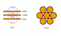
So, let's refer to FIG.1, it's a cross section view of three adjacent layers in a flat foil coil, it looks like a sandwich. The proximity effect at the middle layer comes from its next upper layer and lower layer, as shown in the figure the external magnetic flux from the upper (blue circle) and lower (red circle) layers cancels each other at the middle layer. So proximity effect probably is insignificant in flat foil coils. The only exception is the very first top layer and the last bottom layer of the flat foil coil.
And FIG.2 is a cross section view of a typical wire-wound coil, each central wire typically has six adjacent wires around it, there are some external magnetic fluxes from the six adjacent wires that cannot be cancelled by each other in the central wire, I have drawn some blue arrows to indicate the possibly not cancelled flux's locations.
So in a wire-wound coil, the proximity effect and skin effect both exist, it's more complicated than a flat foil coil.
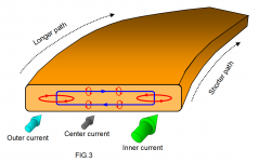
FIG.3 is a 3D cross section view of a flat foil coil, the 3D round arrows and their sizes indicate the inner(green), center(gray) and outer(blue) currents and their magnitude (inner current > outer current > center current) at high frequencies.
At the foil's cross section area, the blue circle indicates the internal magnetic flux of the foil currents, and the red circles indicates the induced Eddie currents (back EMF).
At high frequency, the center current is mostly decreased/cancelled by the reverse-direction Eddie currents, inner and outer currents are enhanced/increased by the same-direction Eddie currents .
But since the outer current has to run a longer path in the loop, which means the outer current's path has a larger AC resistance, so more current will choose to run through the inner side due to the smaller AC resistance there. As a result, at high frequencies, we have Inner current>Outer current>Center current, and it causes the effective diameter of the flat foil inductor to reduce.
I would say a flat foil coil's reduction of effective diameter at high frequencies is a result of skin effect and the difference in inner/outer path length (how should we call it? Path length effect?).
Hope I got it right.
Attachments
For the flat foil coil, the predominant proximity effect will be that of the solenoidal field. Your section does not include that.
Jn
You are right, I did not consider the proximity effect from the solenoidal field.
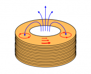
I hope I've got it right in the following figure, it seems that the solenoidal magnetic field (blue lines) will induce eddie currents (red circles) at the first top layer and the last bottom layer of a flat foil coil, but the other layers in between should be basically shielded by the first layer and the last layer.
I think if the proximity effect from the solenoidal field is predominant, then we should be able to observe an increase in the effective diameter because this proximity effect enhances/increases the outer current and decreases the inner current of the coil (see red arrows & their size).
But on the contrary, according to my previous measurements, the effective diameter of a flat foil coil was decreasing as the frequency increasing.
So my conclusions remain unchanged:
1. proximity effect in a flat foil coil is insignificant
2. skin effect and "path length effect" caused the decrease in effective diameter.
It seems to be another benefit of the flat foil coils that the first top layer and the last bottom layer are providing a natural shielding for the other layers in between.
Dr Sullivan's research seems not including the flat foil coils, it is probably that currently the thin flat foil coils are still not available for transformers, yet.
If I were wrong about anything, please let me know. Thanks!
Attachments
From your post #16, you note the current pulls to the ID as frequency increases and the inductance decreases. That is proximity effect. Also as a consequence of this pull in, the Rs of the coil increases.
The top and bottom layers do not shield the entire center from time varying magnetic fields, the inner layers contribute to that solenoidal field.
As you have shown, your inductor design has a large frequency dependence for both inductance and resistance. That might be useful in some designs, but not for others.
As a note: It is very pleasing to see you measure your inductors for L and R vs frequency. When I measure, I will use frequencies that evenly space on a log chart. 20, 50, 100, 200, 500, 1000...etc. Graphs nicer, and as you go up in frequency you can watch the behavior of the test set. Use Ls/Rs mode, and be aware that as the frequency goes up eventually your meter will be lying to you due to distributed capacitance mucking up the phase shift the meter looks for.
jn
From your post #16, you note the current pulls to the ID as frequency increases and the inductance decreases. That is proximity effect. Also as a consequence of this pull in, the Rs of the coil increases.
The top and bottom layers do not shield the entire center from time varying magnetic fields, the inner layers contribute to that solenoidal field.
jn
I have been trying to figure out the proximity effect you have mentioned.
In the following link it did have talked about an one layer foil inductor (fig.2) and its proximity effect. But its foil is vertically rolled (pretty thin in radial direction), not in horizontal flat direction.
http://ridleyengineering.com/images/phocadownload/13%20proximity%20loss.pdf
After reading the PDF above, I would think that a spiral foil coil has a big problem with proximity effect due to its multi-layer structure.
While luckily the flat foil coil has only one layer.
And I have a correction to make (sorry to everyone!).
In my post #36 the figure was not correct!
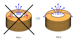
The external summed-up solenoidal magnetic fields of an inductor can never penetrate its own copper wires. (Why? I would leave it to you.)
So I put a big cross on FIG.1 and corrected it to FIG.2 below.
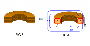
And for displaying the proximity effect, I cut the flat foil coil in half as in FIG.3 (just like a donut in half), and simplified it into FIG.4 with two copper cross section A and B. Currents are flowing out of paper at cross section A and flowing into paper at cross section B.
In FIG.4 the blue lines (H1 & H2) indicate the fields created by A's currents that penetrate B (proximity effect), and red line (H3) indicates the skin effect filed from B's current itself.
Considering the distances from their respective centers of the blue fields and the red field, red field must be much stronger than blue fields, but both of them contribute to the redistribution of currents in B.
Red field will draw the current toward the inner and outer sides. But path length effect (ohm differences) will affect the redistribution of currents between the inner side and outer side.
Blue fields will draw the currents toward the inner sides.
The result is the reduction of effective diameter.
Am I doing it right this time? Comments are welcomed!
Attachments
- Status
- This old topic is closed. If you want to reopen this topic, contact a moderator using the "Report Post" button.
- Home
- Design & Build
- Parts
- Flat Foil Coil - Introduction