At such levels, Mark's remark that Ohm's law in metallic conductors only holds when drift velocity is negligible compared to thermal velocity just might become relevant; 1 mm/s is only 180 dB below 1000 km/s, if you may take 20 dB * log10(ratio).
Does anyone know if, besides Seebeck (thermocouple) effect, anything exotic happens at the end connections? Are the contacts between the resistor body and the terminals purely ohmic?
Terminations in general are a quality control issue, the crimped end caps on film resistors are a potential failure point if only to become intermittent or non-linear. Very high accuracy wirewounds have similar problems, even if welded. Bulk foil resistors are design critical as tolerance increases, every aspect of the design contributes to stability and linearity. Even then, there is a tiny amount of drift over time and useage; Vishay offers pre-aging procedures to mitigate it.
I'm starting to consider for the first time using c0g capacitors to replace silver mica and polystyrene and ceramic types (highly linear glass capacitors are almost unobtanium). I think this'd be a subject for its own thread: what are the non-linearities of 'small' capacitors and what are the best through-hole c0g capacitors that might become 'audiophile grade' parts?
At such levels, Mark's remark that Ohm's law in metallic conductors only holds when drift velocity is negligible compared to thermal velocity just might become relevant; 1 mm/s is only 180 dB below 1000 km/s, if you may take 20 dB * log10(ratio).
3rd order non-linearity goes with 40dB/decade of amplitude, so only 2nd order non-linearity would possibly be detectable at big scale differences.
Jan,
The Dale military metal film resistors will get you there. Just pick the lowest tempco and run below 10% power rating.
You don't need to go that drastic if you use chains of the same resistors to form the voltage divider. Be sure to zig-zag the resistor layout to reduce inductance.
But there are other tricks to getting opamp pairs to even lower distortion!
Last edited:
Metals don't get non-linear at sustainable current levels. Drift velocity goes up with the square-root of power-density, since power-density = resistivity x current-density^2.Yes, it does, very much so: high-ohm resistors tend to be severely non-linear, and it is a headache for people having to build physical standards for example.
Very thin films (metal, metal oxide or carbon) become non-linear because of the extreme current densities exacerbating exotic effects, like the non-adherence to the strict ohm law.
Wirewound resistors have a much lower current density, but they have problems of their own, like self-inductance, self-capacitance and bulk: imagine a 100Meg WW, even made from the thinnest wire and highest resistivity alloy
A drift velocity of 1m/s in a metal foil is called an exploding foil detonator.
")
High drift velocities also mean very powerful magnetic fields too, due to special relativity.
Its quite hard to measure non-linearity of resistance in something thats heating up at multi-mega kelvin/s rates, I imagine the highest steady-state current densities you can investigate are in ultra-thin metal layers on an actively cooled diamond substrate or similar, where the heat can be removed with great efficiency.
(ie the ultimate thin-film resistor)
You can now see why thin-film resistors are normally on an alumina substrate - the poor-mans diamond.
Hello All,
If I recall correctly Ed Simon’s article shows the results of a 1000Hz test frequency sampled across a resistor bridge. The FFT shows distortion at -170dB ish. The Wheatstone bridge notches out stuff that otherwise would be buried in the real time noise floor. Thermal variations are suggested as the mechanism causing the distortion.
Some resistor data sheets show distortion as one of the data lines. Also there is an industry standard measurement method for measuring resistor distortion. It has been awhile since reading the standard. I do not recall the mechanism of distortion discussed in the standard.
I did do some distortion and impedance testing of a few resistors. It is my impression that resistor distortion is more complex than a single frequency FFT will show.
Jan,
Look at the data sheets to see distortion vs resistance values.
Perhaps latching a resistor into your Bode 100 impedance / phase tester will show that down at the -120dB level that there is capacitive and inductive reactance going on, not just E=IR.
I am thinking that a 30 tone could show more of what is going on with resistor distortion.
Thoughts?
You can now see why thin-film resistors are normally on an alumina substrate - the poor-mans diamond.
We just had a retired "geezer" Christmas get together and the source of our blessed thin film target came up. I turns out this was essentially alchemy and not reproducible. All of our laser trimmed products used thin film right on the silicon. Ppm level performance at +-10V signals.

3rd order non-linearity goes with 40dB/decade of amplitude, so only 2nd order non-linearity would possibly be detectable at big scale differences.
Good point, and you only get even-order non-linearity when there is an asymmetry somewhere.
Hi Jan
You probably know that Bruce Hofer did a presentation on ultra low distortion passives as required for his Audio Precision company.
IIRC his comment on the Zfoil resistors was that they were excellent but not as low distortion as the nominal (quasi-static) temperature coefficient would lead one to expect.
Apparently there are some different mechanisms that balance to produce the ultra low tempco.
But the time constants are not the same so the dynamic cancellation is less perfect.
180 dB is beyond even AP so you may be on your own.
Best wishes
David
Wow! Go away for a night's sleep and there dozons of posts! Thanks guys, I will try to reply where useful, but appreciate all contributions. Learned a lot here!
David, yes I am aware. One application is the feedback chain in say an audio power amp with typical feedback values of 20k and 1k. Bruce's idea applied would use 21 identical 1k resistors, 20 in series. It can be shown that resistor non-linearity from tempco and voltco changes cancel.
The Zfoils achieve low tempco because of matching of resistive element expansion rates to substrate contraction rates with temperature. Indeed these have different thermal constants so may become out of phase with rising frequency.
Jan
What reference is this?
Looks contradictory, typo?
[..]
Best wishes
David
Reference is private communication. And yes, typo, my bad. I mean to say: 'lower values are more non-linear'.
Jan
Jan,
The Dale military metal film resistors will get you there. Just pick the lowest tempco and run below 10% power rating.
You don't need to go that drastic if you use chains of the same resistors to form the voltage divider. Be sure to zig-zag the resistor layout to reduce inductance.
But there are other tricks to getting opamp pairs to even lower distortion!
I have had very good results with those Dale's, yes. In my application the feedback resistor values are either equal (1:1 ratio) or 1:2, and as it is their ratio that determines the gain (and distortion), and they have equal signal levels, keeping them iso-thermal should all but eliminate the effect of non-linearity. But at the -180dB level, every atom counts ;-)
Jan
Jan,
Look at the data sheets to see distortion vs resistance values.
Perhaps latching a resistor into your Bode 100 impedance / phase tester will show that down at the -120dB level that there is capacitive and inductive reactance going on, not just E=IR.
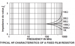
Yes, the impact of parasitic C and L is documented; attached is from Vishay.
I have not been able to find distortion vs resistance graphs - in fact that was the question I had that lead me to open this thread!
Jan
Attachments
Jan if you start with -170 dB resistors and form the chain of identical resistors you should get around -220 dB distortion at 1,000 hertz. As shown in the Linear Audio article this will increase as the frequency drops, but of course less so if the resistors are only used at a tiny fraction of their power rating.
I expect doing that will get you better than -180 at 20 hertz. I would not worry about going lower as the 1/f noise will dominate.
I expect doing that will get you better than -180 at 20 hertz. I would not worry about going lower as the 1/f noise will dominate.
Yes. A collorary: for the Vishay Zfoils, the PCR (Power Coefficient of Resistance) is specified at DC. When the R is heated by a power dissipation, a new equilibrium is reached, at a higher temp, with a changed R according to this PCR.
I am assuming that at AC instead of DC, this changed R due to the same power dissipation with be less than at DC because the R will start to cool before the end situation. In other words, the resistance will be modulated but the 'depth', if you will, the difference between the two values of no dissipation and the given dissipation will be less than at DC.
In the limit at very high frequencies the heating/cooling cycles are so short that the resistance body will integrate the dissipation and the R will change less than at DC. So DC will be worst case for this.
So far so good?
Jan
Looking at how modern resistors are manufactured, contaminants from many different groups could cause non-linearity. I would imagine high purity ultra low-distortion resistors are verrry expensive to build.
jfetter, you have captured the essence of it.
- Home
- Design & Build
- Parts
- What causes resistor distortion?