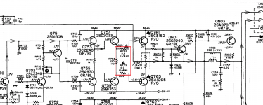
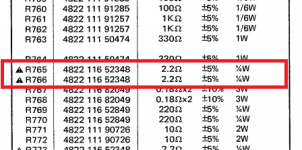
I'm repairing my Marantz PM40SE whose o/p transistor has failed and its emitter series resistor. However I have found elsewhere a resistor whose spec value should be 2.2ohm but is actually 6.4ohm. How is it possible for a resistor to permanently increase in value well outside its tolerance range?
Ian
Ian
Also make sure your meter actually reads around 0.00 ohms when the leads are shorted. Typical test lead resistance might be 0.2 ohm per pair. Make sure the probes make a good connection as well.
High value metal films (over 10k) are a frequent failure item for going high in resistance when used on high voltage supplies.
High value metal films (over 10k) are a frequent failure item for going high in resistance when used on high voltage supplies.
Are you measuring in-circuit?I'm repairing my Marantz PM40SE whose o/p transistor has failed and its emitter series resistor. However I have found elsewhere a resistor whose spec value should be 2.2ohm but is actually 6.4ohm. How is it possible for a resistor to permanently increase in value well outside its tolerance range?
Ian
Your resistor may have blown open and you are measuring the resistance of the rest of the circuit.
Lift one leg so you measure it alone.
Resistors that have been overloaded tend to increase it's resistance but usually by a lot more than a few ohms. Parts of the resistive film can get burned off and the resistance increases. I've had many low ohmic sense resistors measure 10s of kohms after an overload (thickfilm smd types). Perhaps your samples have been just slightly stressed or have simply aged and drifted way off?
But are you sure the resistor is supposed to be 2.2ohm? Could the circuit have been modded without the schematic having the same revision?
But are you sure the resistor is supposed to be 2.2ohm? Could the circuit have been modded without the schematic having the same revision?
Many thanks to all for your replies. I measured the resistor out of circuit with my UT700 meter that has lead compensation zeroing. Resolution is 0.01ohm and accuracy +-(0.3%+60).
This amp has four such resistors in circuit symmetry, but only this one has the altered value so I'll just replace it with one with the specified value.
I should have also asked about the similar resistance increase of the 2x0.18ohm cermet resistor in series with the emitter of the failed output bipolar. I had assumed that very low resistances would be obtained using nichrome or similar wire not metal film. If so how then would this 0.18 ohm (one leg) resistance increase from 0.18ohm to 6.8ohm?
Ian
Wirewound resistors tend to fail at the weld between the resistance wire and the usually copper leads. It is hard to weld dissimilar metals.
Film resistors also may fail at the end caps depending on design.
Film resistors that fail open often have a smudge of carbon bridging the failed spot thus may still show some much higher resistance.
Film resistors also may fail at the end caps depending on design.
Film resistors that fail open often have a smudge of carbon bridging the failed spot thus may still show some much higher resistance.
I had a look at the schematic.....can be useful for ideas, ie prior art.I'm repairing my Marantz PM40SE whose o/p transistor has failed and its emitter series resistor. However I have found elsewhere a resistor whose spec value should be 2.2ohm but is actually 6.4ohm. How is it possible for a resistor to permanently increase in value well outside its tolerance range? Ian


The 2R2 1/4W resistors are fusible resistors to provide protection to the driver transistors in event of output transistor failure and are guaranteed to fail open circuit. In this case the main fuse blew just before the fusible resistor failed as designed.
You question indicates 'novice' status so I will give you some advice from repairing thousands of such gear. First you need a 'bulb tester'. Check all resistors and transistors in the driver and final output stages and replace as required. Any 2R2 resistor will replace the fusible resistors but won't provide the driver transistor protection. It is best practice to use fusible resistors but you also have opportunity to experiment with resistor types ie Metal Film, Metal Oxide, Carbon Film, Carbon Composition etc which may alter/customise 'voicing' of your amp.
Disconnect the output transistors collectors and power up using the bulb tester and check for correct no signal operation ie 0V DC offset, output relay operation. If good you can take a listen into headphones at low level to confirm clean audio. If all good connect collectors and reconfirm DC conditions and set bias current to half of spec. Connect amp directly to AC power and fine adjust bias current then allow the amp to run long term and periodically recheck/recal bias. Connect headphones and take a listen, if good connect speakers and you are good to go, enjoy.
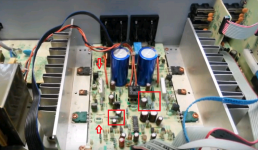
The two boxes on the pic show hot resistors next to capacitors which will cause premature cap failure.....spread them apart to allow cooler running. If you do experiment with the 2R2 resistors mod one channel at a time so that you can compare sounds and form a preference if there is notable change.
Dan.
Last edited:
Dan, You gave me new knowledge. I was not aware of fusable resistors but you were correct my main fuse blew and he fusable resistor overheated, changed value but did not blow. I have now read about ceramic resistors quote: Ceramic resistors are manufactured from a sintered body of ceramic material, with conductive particles distributed throughout the matrix, to produce a resistor that is 100% active and non-inductive. Ceramic resistors are chemically inert. end quote. So now I know why the emitter resistor increased in value.
Although my college education was initially in the valve era I quickly progressed through discrete analog into the digital age then a career in industrial automation. Only now because of audio interest have I returned to learning and practical issues of the analog world. I am so pleased that I found this forum and such helpful people. Thanks for the procedure tips in my work to restore this nice amplifier. It will be powering my present DIY project which is kit building a floor standing transmission line speaker pair. The 40+40W is sufficient for these 88 dB speakers.
Ian
One possibility, your meter is not accurate at such low R value.
A four-terminal (aka Kelvin) measurement is needed for low-value resistors. I use a bench supply set to 1.0A to drive the resistor and measure the voltage across the resistor with a multimeter, simple and easy for sub-ohm resistors. For range 1 to 10 ohms 0.1A is a safer current to use. Probe the resistor right on its terminals/leads, avoiding the cable resistance.
Glad to help you Ian.Dan, You gave me new knowledge......
That quote is a little ambiguous, except for Carbon Composition tubular resistors are are an insulating ceramic rod with coating (matrix ?) of conductive material.
Be sure to use a bulb tester.
Dan.
- Status
- This old topic is closed. If you want to reopen this topic, contact a moderator using the "Report Post" button.
- Home
- Design & Build
- Parts
- How can a metal film resistor increase in value?