Most of the DC operated relays will have a +/- marking for the coils. When the coils are released, the back emf induced will be in the order of a few hundred volts. A reverse connected diode wired will absorb the back emf protecting the driver transistor or the contacts that energize the relay from arcing or in sensitive circuits prevent the spike travel back to other circuits. Since the back emf is opposite in polarity, the diode (conducts) absorbs the energy only when coil is released. This causes an increased delay in magnetic mechanism release time by another 10 milli seconds. In industry all dc relay wiring are polarized even if the relays do not use diodes. This is to prevent accidental shorting of DC power supply if one relay is replaced with a diode model. Some manufacturers provide external diode/RC snubber accessories that can be fitted to the relay bases. RC networks are used in relays with AC operated coils. Diode with resistor will shorten the mechanism release time than a diode itself. Regards.
Nor do I, here's my understanding:The diode is the usual well proven way to protect the transistor.
What is the delay value because of the diode ?
I do not see why it has some damaging effect on the relay contacts. Is this known and proven ?
In most relays the magnetic force is at its peak when the armature iron contacts the pole piece of the solenoid. A spring is trying to pull the armature back. When the current gradually drops the magnetic force reduces until the point the spring wins, Then the armature accelerates away from the pole as the magnetic force drops sharply with distance even if it is changing slowly with time.
The contacts are on another spring which means the contact force doesn't reduce until the armature is already accelerating away from the pole.
So the contacts are unaware of how slowly the energizing current falls, and the circuit is broken just as cleanly with a diode or not.
All assuming the relay is engineered well.
You can test a relay coil using a variable voltage supply and vary the voltage up and down, seeing both the hysteresis in operating voltage and the clean snap of the contacts when closing and when opening. If it doesnt switch cleanly in either direction its likely to be faulty.
Note that you should use some means to protect the supply from back EMF if it doesn't have large decoupling caps to absorb it.
Sometimes folks want the relay to "drop out" as quickly as possible, i.e., with no delay at all. The typical example is a Turn Off Thump preventer / output muting relay. When it's time to mute, you want to mute RIGHT NOW and not 20 milliseconds later. The circuit tricks which maximize the ramp-down of coil current (engineers would say: which maximize |dI/dt| ), give the quickest shutoff.
Since the coil inductance has no other choice but to obey the inductor differential equation |dI/dt| = V/L ...
if you seek to maximize |dI/dt| you can either increase V or decrease L (or both). One of these requires you to be a relay designer, the other only requires you to be a circuit designer.
Since the coil inductance has no other choice but to obey the inductor differential equation |dI/dt| = V/L ...
if you seek to maximize |dI/dt| you can either increase V or decrease L (or both). One of these requires you to be a relay designer, the other only requires you to be a circuit designer.
You may want to get some peak detector before hoping that a 300 volt transistor will work for something like a 12 volt relay. Kickback can be more than you think for a brief moment. I only know from measuring the DC resistance of assorted transformers and coils with an old ohm meter and getting a good kick because I was smart enough to hold the leads with my fingers.
A trick I was taught was to put a Zener in series with the back emf diode.
This helps release quicker.
If the relay drops out quicker there is less chance of contact arcing on DC systems.
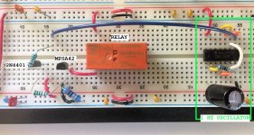
I just put together this experiment on the solderless breadboard.
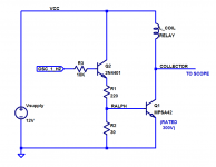
It's a 300V NPN transistor "MPSA42" driving the coil of a 12V relay (33 mA coil current) with no flyback protection whatsoever. No diode, no zener diode, no resistor, no capacitor, nothing. I monitored the collector voltage with my least expensive {most expendable} oscilloscope. Data below.
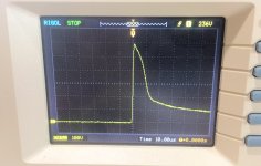
The scope (100 MHz bandwidth) says the collector shoots up to about 600 volts, and dwells in the Super Duper High Voltage realm for about 1.5 horizontal divisions on the scope, namely, about 15 microseconds. "236V" is where I told the scope to trigger, on the rising edge.
Interestingly, the "300V" transistor keeps right on working. I ran the experiment for about 100 on/off cycles of the relay, i.e., about 2 minutes, while I adjusted the instruments and snapped a photo. It was working just fine with no apparent ill effects, when I shut it off.
Resistor R2 ensures that the relay driver transistor Q1 is turned off extremely quickly; R2 sucks out the base charge of Q1 in nanoseconds. Predriver transistor Q1 buffers the input, because the 1 Hz oscillator is made of CD4000 CMOS logic gates (Schmitt trigger inverters) that are barely able to source or sink half a milliamp.
_
It's a 300V NPN transistor "MPSA42" driving the coil of a 12V relay (33 mA coil current) with no flyback protection whatsoever. No diode, no zener diode, no resistor, no capacitor, nothing. I monitored the collector voltage with my least expensive {most expendable} oscilloscope. Data below.
The scope (100 MHz bandwidth) says the collector shoots up to about 600 volts, and dwells in the Super Duper High Voltage realm for about 1.5 horizontal divisions on the scope, namely, about 15 microseconds. "236V" is where I told the scope to trigger, on the rising edge.
Interestingly, the "300V" transistor keeps right on working. I ran the experiment for about 100 on/off cycles of the relay, i.e., about 2 minutes, while I adjusted the instruments and snapped a photo. It was working just fine with no apparent ill effects, when I shut it off.
Resistor R2 ensures that the relay driver transistor Q1 is turned off extremely quickly; R2 sucks out the base charge of Q1 in nanoseconds. Predriver transistor Q1 buffers the input, because the 1 Hz oscillator is made of CD4000 CMOS logic gates (Schmitt trigger inverters) that are barely able to source or sink half a milliamp.
_
Attachments
Thank you! Picture is very clear now (I don't need, but for society).The scope (100 MHz bandwidth) says the collector shoots up to about 600 volts, and dwells in the Super Duper High Voltage realm for about 1.5 horizontal divisions on the scope, namely, about 15 microseconds.
_
I'm shure transistor works as zener here, but only we dont know its avalanche parameters. If we take higher rated voltage transistor - peak voltage could be even higher.
The more I think about it, the more I'm warming to the idea of using a single shunt resistor for transient suppression/coil reset. If the shunt resistor is several times the relay coil resistance, the increase in drive current is tolerable, and you can use a transistor with fairly modest BVCEO rating to handle the transient. The voltage will be impressed across a voltage divider consisting of the relay coil resistance in series with the shunt resistor.
Absolutely true.The more I think about it, the more I'm warming to the idea of using a single shunt resistor for transient suppression/coil reset. If the shunt resistor is "N" times the relay coil resistance, the increase in drive current is tolerable, and you can use a transistor with fairly modest BVCEO rating to handle the transient. The voltage will be impressed across a voltage divider consisting of the relay coil resistance in series with the shunt resistor.
You'll get a slightly faster turnoff (the current flowing in the relay coil inductance+resistance will drop to zero quicker) if you connect a (N x SupplyVoltage) zener diode across the switching transistor. It keeps the across-the-relay-coil-pins voltage higher, which keeps the |dI/dt| higher, which ramps the current to zero quicker. The zener conducts zero extra current in either steady state condition (relay on, relay off). And it's a single component, same as a resistor. Zeners cost about three cents while resistors cost about 0.3 cents.
_
Last edited:
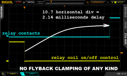
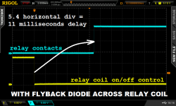
Using the experimental setup in post #28 I measured the turnoff times (a) with, and (b) without, a standard flyback diode (1N4148) across the relay coil.
It shuts off about 5X slower with the diode than without. At least for this relay.
The yellow waveform is "OSC_1_HZ", the rail-to-rail signal produced by the CMOS oscillator circuit.
_
It shuts off about 5X slower with the diode than without. At least for this relay.
The yellow waveform is "OSC_1_HZ", the rail-to-rail signal produced by the CMOS oscillator circuit.
_
Attachments
Why in series? May be in parallel?The voltage will be impressed across a voltage divider consisting of the relay coil resistance in series with the shunt resistor.
Why in series? May be in parallel?
It should be:
At switch off, the current circulates through the relay coil resistance in series with the shunt resistor
To get a shorter switch off delay, the magnetic field must be reduced as quickly as possible. At switch off, the current flowing is the same as before switch off, and it is this current that is maintaining the magnetic field. With a shunt resistor, the voltage falls as the current falls, so the energy (per unit time) dissipated reduces very quickly. With a zener, the current reduces, but the voltage does not, so the energy (per unit time) dissipated stays higher for longer
Hope that makes sense
Brian
I understand. I just want to add, that at the very first moment current doesn't go through that resistor, because a larger part of it goes through an arc between open contacts (or another type switch) and power supply - through it's "usual" way, because it is lower resistance way. And that parallel "series" resistor has larger impedance than a power supply internal impedance.
But it definitely lowers the peak voltage, I agree.
But it definitely lowers the peak voltage, I agree.
Last edited:
Just would caution y'all that you are using terms like di/dt but treating the analysis on a steady state basis. When the coil produces its back emf and turns into a source, it does so as shown in the scope captures, but due to distributed parameters within the coil itself (post 31), this 600V peak may be largely developed across just a few end turns of the coil.
Small pcb relays are wound with many turns of extremely thin enameled wire. Thickness of the enamel is also extremely thin, as you are potentially dealing with 5 or 12V relays. Repeatedly drive a few turns with transients of 600V is a recipe for infant mortality. Perhaps you can try a few hundred times and not have a failure, but I would not be comfortable with the long term reliability of this approach. Seems like adding a 100V zener has some advantage in meeting somewhere in the middle.
Small pcb relays are wound with many turns of extremely thin enameled wire. Thickness of the enamel is also extremely thin, as you are potentially dealing with 5 or 12V relays. Repeatedly drive a few turns with transients of 600V is a recipe for infant mortality. Perhaps you can try a few hundred times and not have a failure, but I would not be comfortable with the long term reliability of this approach. Seems like adding a 100V zener has some advantage in meeting somewhere in the middle.
Do relay manufacturers share your fear that operating their relay coils with no flyback clamping, degrades reliability? I've only read three or four dozen relay datasheets and application notes, but I've never seen such a warning in any of them. Have you?
I'd imagine that if it were dangerous in any way, datasheet writers would strongly caution against it and/or explicitly forbid it.
In fact I'd imagine that if it were dangerous not to have a flyback clamp, relay manufacturers would include the clamp diode right inside the relay every time. But they don't. They offer it as a purchasing option. Want a relay with diode across the coil? Sure we sell those, part number 1234-A. Want a relay with no diode across the coil? Sure we sell those too, part number 1234-B.
If it's so bad how come nobody else is saying so?
The relay coil may be rated for ac and dc, or be connected differentially between two signals to provide an XOR function - standard relays can't assume the coil driver circuit has a polarity because then they wouldn't work in many circuits that happen to have the opposite polarity.
Datasheet authors assume the reader understands what an inductor is and that switching inductors requires kick-back protection of some sort.
Datasheet authors assume the reader understands what an inductor is and that switching inductors requires kick-back protection of some sort.
- Status
- This old topic is closed. If you want to reopen this topic, contact a moderator using the "Report Post" button.
- Home
- Design & Build
- Parts
- Relay coils polarity, why some matter and others dont ?