This is the first time anyone mentions: "have too small ESR to damp resonances.". My initial response is WTF.
Schematics deal with ideal components, a capacitor has capacitance only. In the real world, there will be ESR and ESL in a capacitor and I have learned that it is undesirable and one want these values to be generally low.
Have you all assumed that using ESR to dampen resonances is in the public domain and every knows ?
It's not that you want a non-ideal capacitor, it's that the rest of the circuit is also non-ideal.
It is public domain and in dozens of PDFs on decoupling you can find with a Google search.
Become friends with your enemies. It will be a love-hate relationship from now on .... LOL.It's not that you want a non-ideal capacitor, it's that the rest of the circuit is also non-ideal.
It is public domain and in dozens of PDFs on decoupling you can find with a Google search.
Thanks ... I needed that ... apparently ... LMAOAnother audiophile saved from being lost to the dark side. Well done Jedi knights.
Let us do some counting:
(post 12)
(post 15)
(post 16)
(post 19)
(post 22)
(post 24)
(post 30)
(post 71)
I make that eight mentions of this point. Did you miss all these posts?
Let's do that, I'm all-in!
post 12 - excellent, so you guys are discussing "electrolytics" as they are the only type, you said it!
post 15 - good points.
post 16 - uhm, on the edge ... I'd say try again, but who's me?
post 19 - try again.
post 22 - try again.
post 24 - try again.
post 30 - even I got a bit confused ..
try again? Now to the question - Did YOU miss the point that they are not comprehensive enough? Not my place to say anyway. #Discuss (if anyone will)
What I think is that good bunch of you people, must learn to make the replies that the author of the thread needs, this is not a forum where kids argue about video games, one can get serious health issues, should one be so incompetent and try things out.
The author should definitely learn to not feed the trolls.
Begs the question, what should I learn? Not to get involved.
I'm eagerly waiting to read something I don't know, just if you guys think I'll reply again, you need to do something else, again.
Darrow out.
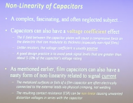
to my understanding these 2 slides in OP were shown as an example for non-linearity of film caps, particularly ESR dependance on current, which was indicated in the previous slide.
still did not get from the discussion above, is that a valid concern or not?
still did not get from the discussion above, is that a valid concern or not?
Attachments
Not for reservoir capacitor in power supply applications.
That's what people have been trying to tell all the time. It all depends on the app.
The best cap for a power supply reservoir is an elcap, not a film.
For coupling cap, film caps are much preferred over an elcap.
It seems from the context that that slide was also talking about coupling (or maybe filter) apps.
Jan
Member
Joined 2009
Paid Member
I can think of an exception - and it's fun doing so, so why not - for tube amplifiers where there is a fair bit of heat, where voltages are high and where currents tend to be low, a film cap based power supply may make sense - lifetime of the caps under the chassis could be much longer in those cases.
We gave the reply he needs, but not necessarily the reply he wanted. It gradually emerged during the thread that his understanding of electronics was even more limited than we at first assumed. I am not aware of any trolling in this thread until now.
At the same time as the frustration of the ideology before understanding (and we all do it, at least somewhat, maybe not in audio but elsewhere), it was a far more fruitful discussion than the typical cap rolling thread. I'm as guilty as any, but we should at least try to give credit for the op's attempt at being data driven.
Not for reservoir capacitor in power supply applications.
That's what people have been trying to tell all the time. It all depends on the app.
The best cap for a power supply reservoir is an elcap, not a film.
For coupling cap, film caps are much preferred over an elcap.
It seems from the context that that slide was also talking about coupling (or maybe filter) apps.
Jan
thanks, any comments on how this translates to use of film vs ceramic in LPFs?
^ LPF is the most demanding use for caps; depending on the surrounding impedances and the target frequency, you're looking at anywhere from 10s of uF to nF, thereby that may require a high quality bipolar electrolytic, film cap, or perhaps a ceramic. That depends on capacity needed vs physical size/EM coupling vs environmental conditions, etc.
I wish I could give you a better answer than, "it depends", but one can take solace in the quality of modern components. There's been a few measurements through the years of distortion across modern bipolars, and even in the "filter" region (versus coupling), they appear very well behaved.
I wish I could give you a better answer than, "it depends", but one can take solace in the quality of modern components. There's been a few measurements through the years of distortion across modern bipolars, and even in the "filter" region (versus coupling), they appear very well behaved.
Something else occurred to me. The OP strongly suggested that more accurate parts were 'better'. For instance, a 1% cap would be 'better' than a 5% cap, all else being equal.
This is incorrect. The 1% only means that the manufacturer spend some time to select a nominal cap from the manufacturing batch, and you pay extra for that of course.
The only time this is important is when you have for instance a filter circuit that depends on two or more caps being equal in value. For instance, in a twin-tee notch you need three caps, two equal and the other double the value of the others. Having 1% parts helps for a good filter curve, but also costs you.
But other than that, a 1% cap is not 'better' than the same cap with 5% tolerance. A 10.1nF cap is not 'better' than a 9.6nF cap.
Jan
thanks, any comments on how this translates to use of film vs ceramic in LPFs?
Don't use anything but C0G/NPO ceramic in filters, unless you mean power supplies - then you can use X5R or X7R.
Don't use anything but C0G/NPO ceramic in filters, unless you mean power supplies - then you can use X5R or X7R.
I suppose you do not mean that for instance FKP2 film caps would be bad choice for post DAC LPF?
actually, recently I was playing with equal value different cap types in I/V opamp FB path. ceramic vs film vs silver mica. the last one sounded the best. I would think that there was something beyond just isolated cap type, rather than which one fits the best in the whole design. kind of matching the cap to the opamp, PCB topology, trace with etc. and there are some high-end DAC designs which proudly claim "ceramic free"
Sorry, I meant, if you go with the ceramic. Polypropylene is fine. I would not use the silver mica, however. It's a lousy performer compared to PP and C0G.
I would almost always use the C0G ceramic instead of FKP2 though because FKP2 are huge in comparison and the layout can be much better with C0G, less chance of RF pickup, etc. In practice, C0G and FKP2 both measure very well.
Any design bragging about being ceramic free is uninformed, in my opinion, and likely talking about the Class II dielectrics anyway. There is a world of difference between X5R and C0G.
it can be argued that parallel C0G is still a viable option volume for volume.
The usual metric is CV product. Roughly cap dimensions size with both C and V. So a 100uF 250V cap can be expected to be somewhat the same, volume-wise, as a 250uF 100V cap. It's no hard law but useful for a first approx.
Jan
This is marketing, not engineering. Because some ceramic caps are nonlinear and should not be used as coupling or filter caps some people then think that all ceramic caps should not be used for any purpose in audio equipment. I guess there are some 'designers' who think like this.eziitis said:. . . and there are some high-end DAC designs which proudly claim "ceramic free"
For some purposes (e.g. local decoupling) a nonlinear ceramic cap may be the best option. Not because it is nonlinear, but because it is physically small. Avoiding the best option because it will look bad in marketing material is poor engineering although it may be wise economics.
- Status
- This old topic is closed. If you want to reopen this topic, contact a moderator using the "Report Post" button.
- Home
- Design & Build
- Parts
- C0G/NP0 Parallel-Capacitor-Board