Hi,
I have a need for a power R that can withstand one (two actually) high-current pulses, and then go to sleep, so to say.
Resistance about 5Ω. The power pulse will be around 30A for about 50uS. Then, 12 mS later, one more pulse. That's it, until the equipment is switched off and on again.
The peak power in that pulse is of course 4500W for 50uS.
I was looking at a 5.6Ω 10W resistor that is specified as able to withstand 10X the power for 5sec, so 100W for 5sec. If I down-extrapolate that, it comes out to 5000W for 100mS, so much more than that pulse requires.
So my question is:
1. is my reasoning correct?
2. would the 30A current be a limit apart from the power dissipation itself?
Jan
1. Partly
2. Yes
J-P, dirty details please!
I checked the wire size versus current table and for 1mm^2 Cu wire (which is the resistor terminal wire) max continuous current is 16A.
Why would 30A for 50uS then be a problem, and how would that problem manifest itself?
Jan
If your resistor construction is a wire wound type then your maximum ratings with a pulse is defined by how quickly the wire itself in the resistor coupled with the wire feeding the resistor will melt and consequently destroy the continuity of the load.
A 1mm copper wire is rated at roughly 16A continuously, but will withstand a greater amount of current for a split second. The amount of time depends on external temperature etc at will your resistive load.
A 1mm copper wire is rated at roughly 16A continuously, but will withstand a greater amount of current for a split second. The amount of time depends on external temperature etc at will your resistive load.
If your resistor construction is a wire wound type then your maximum ratings with a pulse is defined by how quickly the wire itself in the resistor coupled with the wire feeding the resistor will melt and consequently destroy the continuity of the load.
A 1mm copper wire is rated at roughly 16A continuously, but will withstand a greater amount of current for a split second. The amount of time depends on external temperature etc at will your resistive load.
That's what I thought. 30A for 50uS should qualify as 'split second'I think
")
Jan
AFAIR Isabellenhütte datasheets are quite detailed, when it comes to pulse loads. Maybe you could squeeze out something useful out of them.
Excellent tip Jürgen!
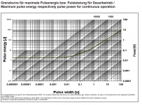
I found the attached graph. I interprete it as follows:
I follow the slanted curve which starts at the right scale at 10W, which goes down to the crossing at 1 Joule and 0.1s. So I assume that the 10W unit can handle 1 Joule for pulse widths not to exceed 0.1 seconds.
In my application I dissipate about 0.5 Joule at a pulse width of 50uS. Seems 'no sweat'. Assuming I interprete it right, of course.
Jan
Attachments
Wirewound Pulse and overload application notes TT Electronics
http://www.ttelectronics.com/themes...ts/resistors/literature/Pulse-Overload_AN.pdf
http://www.ttelectronics.com/themes...ts/resistors/literature/Pulse-Overload_AN.pdf
RJM1, that's exactly what I need! For me, for the very short overload (50uS pulse width) the graphs on page 7 would apply and specify the overload in terms of voltage across a resistor. For instance, the allowable voltage across a 5 ohm R is some 200V. Insane pulse power (8kW) - but thankfully it will only last 50uS according to LTspice!
The resistors I want to specify are from another manufacturer (OHM) but I'm pretty sure they all have similar specs for similar resistors.
Thanks!
Jan
The resistors I want to specify are from another manufacturer (OHM) but I'm pretty sure they all have similar specs for similar resistors.
Thanks!
Jan
Just checked the PR01 to PR03 resistor datasheet - the PR03 part has a 220W 50us max capability, with a 1000:1 duty cycle - so would have to use the 200:1 duty cycle which allows about a 180W capability. That datasheet has some good data on temp rise that is not typically shown in other resistor datasheets. If you wanted to go a compact, multiple parallel resistance path, then 25 of those parts with 120 ohm value would cover your application, and be off the shelf and possibly quite economic.
https://www.vishay.com/docs/28729/pr010203.pdf
https://www.vishay.com/docs/28729/pr010203.pdf
- Status
- This old topic is closed. If you want to reopen this topic, contact a moderator using the "Report Post" button.
- Home
- Design & Build
- Parts
- Single pulse surge in resistor