Hi everyone ! I am not shure if this post belongs here or in the source/line forum.
I am currently designing an input selector module. I plan on using it in the 4S preamp I am currently building http://diyaudioprojects.com/Tubes/Universal-Tube-Preamplifier/. If my design reaches my expectations, I may build an other one in a separate enclosure. I have a mitsubishi da-p20 preamplifier that I really like, but it only has one "aux" input...
The question is : I don’t know how to power my selector. My preamplifier mains power transformer has a 6.3v 2.5a heater supply, but it doesn’t have a center tap. On the other hand, I feed my preamplifier with clean 250VDC, but it’s way too much to power relays, LEDs and FETs.
With the added input selector board in the enclosure, space begin to be an issue so I need a simple solution with the fewest parts possible and/or the smallest footprint. Not having to run ac wires around the "signal side" of the preamp would give me more flexibility. DC heaters would then become an interesting way around this problem because the low tension supply could also be used to power my input selector, given that it’s powerful enough to power everything.
Is there something i am missing ? Any hint or information is appreciated !
DC heaters would then become an interesting way around this problem because the low tension
supply could also be used to power my input selector, given that it’s powerful enough to power everything.
That sounds ok, unless you need to elevate the filaments above ground to reduce hum.
Last edited:
I don’t know how to power my selector.
How about this hand powered selector ?
https://www.ebay.com/itm/2P3T-2-Pole-3-Throw-1-Deck-Band-Channel-Rotary-Switch-Selector-with-Plastic-Knob/183497397338?epid=2296050391&hash=item2ab94c145a:g:m84AAOSw5SpbzXJC:rk:1
 f:0
f:0
My selector uses 12V. How many do you need?
The only thing I really need is a way to select my inputs. Do i absolutely need to use relays ? I don’t really like the idea of having my input signals running around the enclosure through the rotary switch. I need a way to power my leds anyway so using relays seemed to make sense. But while drawing my schematic, I realized that I need low tension dc to make this possible.
I really don’t want to use a second ac/ac transformer.
Most people use a hand-powered rotary switch for input selection. Some use a very long shaft so the switch is near the back panel but the knob still is at the front.
Your answer kind of confirm what I was thinking last night. Only the LEDs need to be sorted...
Only the LEDs need to be sorted...
How many inputs do you need ?
With a 3 pole 3 throw rotary switch you can handle 3 stereo inputs + 3 LEDs.
Rotary Switch 3A 350V Ceramic 3P3T 3-pole 3 throw 3-position Silver Contacts | eBay
But where do i get my power for the leds ?
From here:
My preamplifier mains power transformer has a 6.3v 2.5a heater supply
This should get the LED lit.
Attachments
I use these: 6 Channel Unbalanced Stereo or Balanced Mono Audio Input Selector Relay Module | eBay
They are cheap and cheerful and can be placed next to the RCA jacks... The switch switches 12V to the relays.
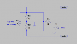
And the drawing above: connect the LEDs to the heater winding, or the HT winding... If the latter you need a 2W 100k ish resistor for each LED though...
They are cheap and cheerful and can be placed next to the RCA jacks... The switch switches 12V to the relays.
And the drawing above: connect the LEDs to the heater winding, or the HT winding... If the latter you need a 2W 100k ish resistor for each LED though...
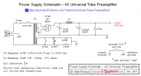
This is the psu i’ll be using. Could you tell me where i should conect the LEDs ?
The LED goes between the bottom of the 470k resistor and ground,
with the LED's cathode connected to the ground.
You will likely need to reduce the value of the 470k to perhaps a 250k at 0.5W
to get enough brightness from the LED. Then the bleeder/LED would take 1mA,
instead of 0.5mA as with the 470k.
Last edited:
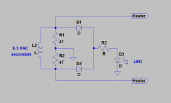
A "small" correction to my drawing. Two diodes were missing.
It makes so much sense now ��
I am way to deep into diy audio to have such a minimal understanding of ohms law. I will do my homeworks this weekend. I don’t know how to calculate the values of this kind of things
Last edited:
- Status
- This old topic is closed. If you want to reopen this topic, contact a moderator using the "Report Post" button.
- Home
- Design & Build
- Parts
- Tube preamplifier input selector question