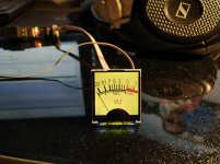
Hi there, for my crazy-tiny sized PowerDAC project(157x108x34mm) I needed some compact VU meters to fit that in my front panel. I checked all possible sources and find that no real-electro-mech VU less than 20-30mm of depth, just doesn't exist. The same time I noticed proposals for LCD surrogate VUs, mostly looked ugly(DIYers made) and unrealistically expensive for MCU+LCD device($77-200 and some has arrows aren't smoothed-ladders!). Next, I decided to spend a week of my time to build a compact IPS display based VU meter. LCD IPS means good angles of view and realistic color representation(at least 100% sRGB). I found a few suitable LCD and tried first of them 1.3" with SPI interface. That was damn slow screen, even if I upload my data into its memory with 17FPS rate, the screen will show 6FPS rate and no more! It is too slow for an arrow dynamic representation. Next one 1.5" 8080 8bit interface performs 23FPS with STM32F030C8, and it looks quite ok if not to say nice! I prepared a close copy of classic Teac VU meter bitmap, fit that into 240x240pix(225ppi almost retina) with antialiasing and 30 arrows positions. The short Matlab script compresses bitmaps to indexed colors sequences and packs that into the C header file. So, the process of porting any view of original VU meter is automized. Only 43 of 64KB is used now, hence I have a room for some clock(for instance, MB cars has dash panel clocks nice looking) function, automatically switch On if 5 mins no input for VU. Or I can add arrow's patterns for better angular resolution. I plan one radio button for auto calibration VU meter: you set an input voltage according to your max power from 25 to 250W@8ohm, and push the button, calibration is finished. I think the final device(35x31.5x4mm 3 pins interface: GND/3.3V/Input) cost should be around $10, and If I'll see any DIYers interest to that beast, I'll order control-PCB assembly 
https://www.youtube.com/watch?v=hdL3nKfYzlk&t=11s
https://www.youtube.com/watch?v=hdL3nKfYzlk&t=11s
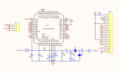
Just finished test of PCB assembly. VU meter is able to work with any voltage sources within 1:45VRMS i.e. may work with 3.3V powered DAC(typical laptop headphone jack or smartphone etc) output or 2000W@4ohm H-bridge amp whatever. Calibration for the particular level performing by providing the level on the UV meter input and shorting "Calibration" pin to GND. The device memorize calibration in its flash memory and recall it every powerup.
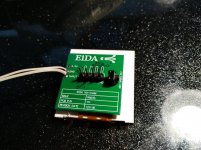
The PCB glued on the rear side of IPS panel by weak glue in case if as thin as possible construction required(PCB and panel tied with kapton flex-cable 40mm, panel thickness 2mm, PCB with parts 3mm). C6;C7 setting the time constant for the arrows roll-back and could be modified if needed as well as R/R divider if need to set higher or lower sensitivity.
The PCB glued on the rear side of IPS panel by weak glue in case if as thin as possible construction required(PCB and panel tied with kapton flex-cable 40mm, panel thickness 2mm, PCB with parts 3mm). C6;C7 setting the time constant for the arrows roll-back and could be modified if needed as well as R/R divider if need to set higher or lower sensitivity.
Attachments

- Status
- This old topic is closed. If you want to reopen this topic, contact a moderator using the "Report Post" button.