Last edited:
It looks like a regular Silicon diode, black epoxy cased and all, just with somewhat unusual coloured end caps showing polarity, and if in the High Voltage power supply, an 1N4007 as suggested above will do fine.
We asked for a picture because in the 60´s, you might have found a Selenium rectifier (looks like a stack of stamp sized metal fins) or a Germanium one, which would have been packed inside a glass envelope, or even a Silicon power diode, but inside a metallic case, similar to a thin pencil eraser.
And a Bell and Howell projector must have most probably been made in USA.
This amplifier can be DEADLY if converted to guitar or hi-fi use!! It has no power transformer. One side of the audio is directly connected to one side of the Power Line.
This scheme was common on radios. With a plastic case, radio-waves in, sound out, the user never touched the audio. This could extend to a film projector with only internal source (sound-head) and appropriate well-insulated speaker connectors.
But a 1/4" phone plug, or RCA plug, has the audio exposed on its case. If the line connections are made wrong, the thing plays, but the user can get a 230V shock.
In its defense, I am told that electrical outlets in the UK are polarized and very likely to be wired correctly. (In the US I have seen 60% in one room wired Live/Neutral reversed.) But it must be up to YOU to verify both your outlets (all that you will ever use, even at friends or taverns) and your fresh new line-cord (I would not trust most 50 year old cords).
And many UK outlets are now on RCBs(GFI) which is supposed to cut-out on excess leakage (which may be through a human body, yours). I like them but do not bet my life on them.
Yes, B&H was dominant in the US. However this amplifier looks like UK design. Perhaps B&H hired designers familiar with UK production practices and economics of parts. Perhaps it is actually another make sold under the B&H brand-badge.
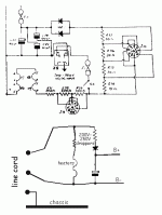
That schematic is drawn as a maze. Here is the core of the power business.
That schematic is drawn as a maze. Here is the core of the power business.
Attachments
Ouch!!!
yes, that´s a *deadly* amplifier, doubly so in 240V fed UK lines, but they were never safe under 115V US mains.
You NEED an isolation transformer, or even better, just cannibalize tubes, sockets and Output Transformers and build any suitable project, WITH a proper Power Transformer of course.
Thanks PRR for pointing this out.
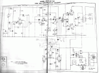
Here’s a copy of the whole schematic.... but anyways I think I might take your advice on reusing the parts to make a proper amp.
http://i1361.photobucket.com/albums/r674/jimmy6122/8AD4413B-A192-451B-892B-3CFCEAA31536_zpslxlkf97k.jpeg
http://i1361.photobucket.com/albums/r674/jimmy6122/8AD4413B-A192-451B-892B-3CFCEAA31536_zpslxlkf97k.jpeg
This one is truly odd. It does have a Mike jack. And it appears to be 1/4" (guitar plug). How can that be safe?
Wander around. The push-pull pentodes at bottom are a power oscillator. This was often done on optical-sound projectors; at the time it could be cheaper than making really-clean low-Voltage DC for the sound head lamp. But it has another tap, rectified, feeding the B+ for the preamp tubes! And if I trace-out the returns, this small B+ supply does not return to the wall-plug. The audio power tubes' B+ supply is line-hot, but the power stage is *transformer-coupled* input and output.
So just as it stands (not considering any failures of 57 year old parts) this is "Apparently Safe" from Mike/Guitar Jack to speaker.
But if someone left rattlesnakes on my doorstep, in a 57 year old basket, I'd be very wary.
Well I changed the diode and replaced the wire which was acting as F2 with a proper 500mA fuse as specified in the service manual and I’m still not getting any heater or HV for the preamp sections. Since the initial idea is to make it into a guitar amp... than I would definitely prefer doing something with a similar preamp stage but change the whole power supply and output sections to suit an EL84 pushpull circuit. Thanks for all the help
Well I changed the diode and replaced the wire which was acting as F2 with a proper 500mA fuse as specified in the service manual and I’m still not getting any heater or HV for the preamp sections. Since the initial idea is to make it into a guitar amp... than I would definitely prefer doing something with a similar preamp stage but change the whole power supply and output sections to suit an EL84 pushpull circuit. Thanks for all the help
Sorry for the zombie thread.
But did you find out why you had no power to the preamp section? I have a 631 that also suffers from no power to the preamp section.
And to those who are worried about me frying myself, I do have an isolation transformer installed.
- Status
- This old topic is closed. If you want to reopen this topic, contact a moderator using the "Report Post" button.
- Home
- Design & Build
- Parts
- Diode ID


