I bought one of those cheaper eBay analog meters and after a bit of research found that nearly all VU "drivers" are just glorified full bridges, leading to poor needle ballistics. My particular meter is a simple 650ohm/500uA DC meter, which requires a linear signal (0-0.325 V) to correspond to the logarithmic power levels.
I found an application note, AN1991 Audio decibel level detector with meter driver, using the SA604A that seems to be perfect for my purposes. The only issue is that my meter goes from -50dB to +5dB, whereas the AN circuit provides an 80dB range. The notes suggest "a 40 to 50dB segment can be 'selected' for higher accuracy," but they don't mention how to go about choosing this segment and altering the components. Would it be as simple as adding additional gain to the input and attenuation to the output, or is there something in this RF-to-audio circuit that I'm missing?
I found an application note, AN1991 Audio decibel level detector with meter driver, using the SA604A that seems to be perfect for my purposes. The only issue is that my meter goes from -50dB to +5dB, whereas the AN circuit provides an 80dB range. The notes suggest "a 40 to 50dB segment can be 'selected' for higher accuracy," but they don't mention how to go about choosing this segment and altering the components. Would it be as simple as adding additional gain to the input and attenuation to the output, or is there something in this RF-to-audio circuit that I'm missing?
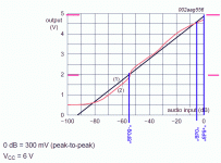
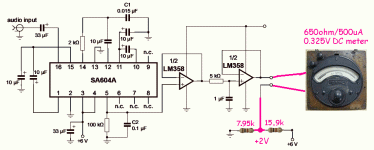
According to Fig. 2, at 55 dB below its maximum input level, the output is at 2 V, and at maximum level at about 4.8 V. Hence, you could connect the minus side of the meter to a voltage divider with 2 V open-terminal voltage and a resistance of (4.8 V - 2 V)/500 uA - 650 ohm = 4.95 kohm. You then still need to add an attenuator at the input to reduce your +5 dB level to 300 mV peak-to-peak.
Assuming an accurate 6 V supply, the voltage divider that generates the 2 V would consist of two resistors, a 14.85 kohm resistor (15 kohm nearest E24 value) to the +6 V and a 7.425 kohm resistor (7.5 kohm nearest E24 value) to ground.
Assuming an accurate 6 V supply, the voltage divider that generates the 2 V would consist of two resistors, a 14.85 kohm resistor (15 kohm nearest E24 value) to the +6 V and a 7.425 kohm resistor (7.5 kohm nearest E24 value) to ground.
I drew before I saw what MarcelvdG described. (Don't know why we got different resistors.)
Designing a *Good* audio level meter is not just some cellphone RSSI pin and adapting it to a needle. Average? Peak? RMS? Peak-Hold? Decay?
Designing a *Good* audio level meter is not just some cellphone RSSI pin and adapting it to a needle. Average? Peak? RMS? Peak-Hold? Decay?
Attachments
According to Fig. 2, at 55 dB below its maximum input level, the output is at 2 V, and at maximum level at about 4.8 V. Hence, you could connect the minus side of the meter to a voltage divider with 2 V open-terminal voltage and a resistance of (4.8 V - 2 V)/500 uA - 650 ohm = 4.95 kohm. You then still need to add an attenuator at the input to reduce your +5 dB level to 300 mV peak-to-peak.
Assuming an accurate 6 V supply, the voltage divider that generates the 2 V would consist of two resistors, a 14.85 kohm resistor (15 kohm nearest E24 value) to the +6 V and a 7.425 kohm resistor (7.5 kohm nearest E24 value) to ground.
I never thought to have the negative terminal floating. Would that cause issues when the input signal level falls below 55dB and the meter gets -2v?
I drew before I saw what MarcelvdG described. (Don't know why we got different resistors.)
Designing a *Good* audio level meter is not just some cellphone RSSI pin and adapting it to a needle. Average? Peak? RMS? Peak-Hold? Decay?
Thanks for the illustrations. I hadn't put much thought into furthering the quality of the meter, since I don't have many references to compare to. The goal is to have something like the Onkyo Integra M-508, which after reading the manual states "The peak power meters have been designed so that the indicator needles move up to the peak level quickly and then return more slowly. This makes it easier to read transient power levels which last for only a fraction of a second."
Digging deeper into the service manual, it notes that the VU meter driver is the TA7318P, which is the IC that's already in-use with my current driver board. Maybe it's the supporting circuitry or the meters themselves that make it look so nice. I'll have to look further into the schematic when I get out of work.
Note also that the "audio" input impedance is 1.6k, a rather low value for audio lines.
Should I add an opamp buffer to the input side then? I have a 15VAC transformer already being used for an amplifier that I can pull rails off. I can also add the attenuation potentiometer into the feedback loop of said opamp for input-level tuning.
I never thought to have the negative terminal floating. Would that cause issues when the input signal level falls below 55dB and the meter gets -2v?
It will drive the needle way into the left corner, but probably without damaging it. If you want to prevent that the meter gets driven negatively, you could replace the LM358 with a rail-to-rail dual op-amp and add a diode between the output and the feedback point of the right op-amp, so the output can only source and not sink current.
Note also that the "audio" input impedance is 1.6k, a rather low value for audio lines.
If that 1.6 kohm is sort of linear, you could use it as one branch of the input voltage divider that reduces the sensitivity. If it is the 2 rpi of the first differential pair, that won't work well.
Designing a *Good* audio level meter is not just some cellphone RSSI pin and adapting it to a needle. Average? Peak? RMS? Peak-Hold? Decay?
Average of the logarithm of the absolute value, judging by the bits and pieces of the internal circuitry you can find on page 6 of this datasheet: https://www.nxp.com/docs/en/data-sheet/SA604A.pdf The filtering time constants are set externally, by the RC network connected to pin 5 and the one between the op-amps. You could decide to hardly filter pin 5 and put a quasi-peak detector behind the whole thing if you want it to behave closer to a peak detector.
So far we are adding a below-zero suppressor, an input buffer, a quasi-peak detector, which includes attack/release time constants.....
So what is really left is the chain of clippers to give a rough approximation of "log". Which really could be a couple diodes on an opamp.
There are many ways to skin this cat. Maybe without needing a lot of side-dishes to finish the meal.
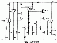
This was good enough for the BBC:
So what is really left is the chain of clippers to give a rough approximation of "log". Which really could be a couple diodes on an opamp.
There are many ways to skin this cat. Maybe without needing a lot of side-dishes to finish the meal.
This was good enough for the BBC:
Attachments
The input buffer is not needed if you want a +5 dB level far above 150 mV peak, just make a voltage divider with the internal 1.6 kohm. The quasi-peak part can be left out if the thread starter doesn't require quasi-peak detection, otherwise it can probably be combined with the below zero protection. I don't believe for a moment that that BBC circuit has 55 dB of range.
Last edited:
- Status
- This old topic is closed. If you want to reopen this topic, contact a moderator using the "Report Post" button.
- Home
- Design & Build
- Parts
- Logarithmic VU/Watt Meter Driver IC


