Howdy. I'm thinking about an electronics project which isn't audio but rather a ZVS induction heater based on the Mazilli Flyback converter. Cheap eBay models have caps which produce large amounts of heat and run at too low a resonant frequency. As I browsed the likes of Wima FKP 4 caps I note that dissipation factors for 100kHz aren't shown for capacitance greater than 0.1uF. I'm looking at a design with 6 x 0.22uF capacitance and a work coil which would target a resonance of circa 135kHz. Obviously I'd like to minimise heat emission from the caps. So wondering why dissipation factors aren't provided for these.
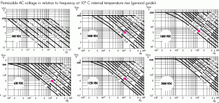
The first Wima FKP 4 datasheet I found does list temp rise. For 10 deg C rise, a 0.22uFd can only be worked at 50V-60V, kinda no matter what the cap's DC voltage is.
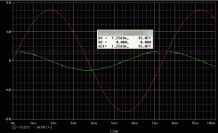
Obviously there is current. A quick sim for 0.22u 70V(pk) 135KHz gives 13 Amps peak, which is a lot for a small part if worked continually.
Obviously there is current. A quick sim for 0.22u 70V(pk) 135KHz gives 13 Amps peak, which is a lot for a small part if worked continually.
Attachments
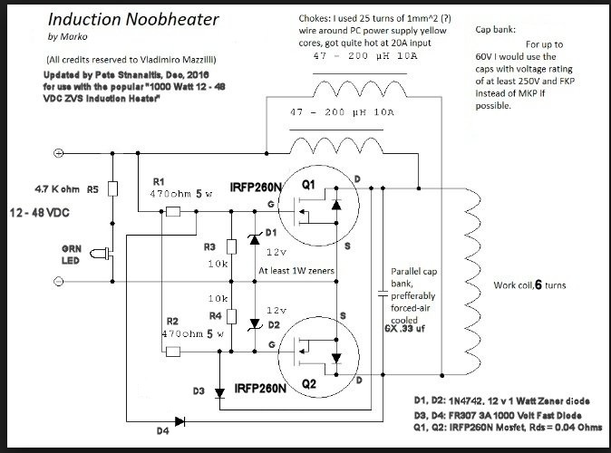
Hi. Thanks for pointing out how to read that part of the datasheet correctly. I hadn't made it into simulating the circuit yet. The eBay purchased model's circuit is this:

and the circuit was originally developed by Marko who is this guy: 500W Royer induction heater | Marko's science site.
With my work coil (not the supplied one - see below) the eBay board (with 6 x 0.33uF) runs at 104kHz. I am powering it via a Mean Well RSP-750 48V PSU. [Surprisingly, for me at least, limited at circa 12A the supply only produces about 38V DC. Not sure why given the PSU is operating well within spec.]
I see Vpp of 218V (77Vrms) and a frequency of 104kHz on my scope when probing across the coil. This is relatively close to the 110kHz resonate frequency computed via f = 1/(2*Pi*SQRT(L*C)) when using 6 x 0.33uF of capacitance and 1.056uH for the work coil (air coil, 7 turns, 1.25" diameter and 1.25" length).
The caps produce a lot of heat and for the annealing application I want commercial implementations run at frequencies starting at 135kHz. So I started to look around for low dissipation caps and noted the original author's comment re caps in the original schematic.
What did you sim to get your current estimate? Of course the sinusoidal current would be spread over the 6 parallel caps.
Last edited:
Of course the sinusoidal current would be spread over the 6 parallel caps.
The parasitics in the capacitor bank have to be carefully balanced to force proper
current sharing among them.
Give Panasonic and Kemet's polypropylene a try. I have measured lower DF at 100kHz from some of their caps compared to Wima. Size matters plus pick the stacked version vs the wound version.
The coil placement matters too. It is meant to heat/metal metal including the aluminum inside the capacitors.
The coil placement matters too. It is meant to heat/metal metal including the aluminum inside the capacitors.
- Status
- This old topic is closed. If you want to reopen this topic, contact a moderator using the "Report Post" button.
- Home
- Design & Build
- Parts
- Cap dissipation factor for 100kHz

