Hello,
Recently bought a KA-5090R amp and only after getting home realized, that the rotary input selector is having an issue with jumping between inputs rapidly. This is a know issue and repair is fairly easy (contacts need cleaning) but as it sometimes goes with diy repairs - I broke the switch and now I am looking for a replacement but all I found was some German site claiming, part is no longer being sold. From service manual I got part number - s60-0032-05, maybe someone has an idea where to look? I'm thinking that I could do one of two things, - either re-solder just the switch or replace the whole input module. Module has two codes on it - "X11 H/10" (this one I assume refers internally within the service manual) and other one is "th11 94v-0". I would really like to avoid buying a broken amp just to get this one switch, as this is somewhat common issue and no guarantee that the other one won't have the same issue.
I have applied some super glue on the little plastic part which I broke off, hoping it will hold at least for now, but I want to replace it for peace of mind.
Maybe I don't know how the internet works, but I failed to find datasheet for this switch. From the schematic, seems that it's 1 pole 12 position switch, but what seems odd, is that when it was open, I noticed there were two connectors which push against the base plate, meaning at any given moment, two connections are made. Maybe because of LED indicators? I'm thinking, what switch I should look for as a replacement? Simple 1p12p would mean 12 individual positions, while I need 6 pairs (I assume). Hoping someone here has disassembled one of these. Your help would mean a lot!
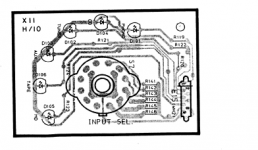
Schematic for the input module attached.
Schematic for the input module attached.
Attachments
6 pole 2way switches are available if that is the sort of thing you need.
https://cpc.farnell.com/lorlin/ck1030/switch-2pole-6-pos-metric/dp/SW04137?st=lorlin
https://cpc.farnell.com/lorlin/ck1030/switch-2pole-6-pos-metric/dp/SW04137?st=lorlin
According to the board the leds aren't switched by the the switch. They have separate connections on the right side. It's a 12 pole switch but 6 of them (left ones) are not connected, unless there are other connections on the other side of the board not seen here. Just shunt the inner connections tabs. I believe this just sends some voltage to relays or Microprocessor, which then send back the Led voltages thru the same connector. You are looking for something like this perhaps.
Panel PCB Wiring Rotary Switch 2 Pole 6 Positions 1 Deck 220V-in Switches from Home Improvement on Aliexpress.com | Alibaba Group
The are others from Lorlin UK in which You can adjust positions from 1 to 12 by means of a tab positioning.
Panel PCB Wiring Rotary Switch 2 Pole 6 Positions 1 Deck 220V-in Switches from Home Improvement on Aliexpress.com | Alibaba Group
The are others from Lorlin UK in which You can adjust positions from 1 to 12 by means of a tab positioning.
Last edited:
Hello, MAAC0,
I believe you are right, switching itself is done by relay, as each turn of switch is followed by an audible click on board. And when the original issue, why I opened this tread in the first place occurs, - relay also goes like crazy. Worried that because of this switch I will eventually have to change those as well.
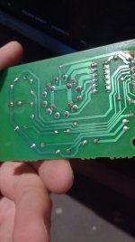
Regarding the connections on board - I've attached two pictures (disassembled the switch again). Switch internals (please notice, in the blue cap, the two copper leads which engage two diametrically opposite connections at any position) and board layout.
EDIT: I wrote this before my coffee. Sometimes surprise myself how I miss so obvious things right in front of me. The two connectors inside are just so that switch could be 'endlessly' rotated and connections would loop through 6 actual connection points. I understand that now, and indeed, 2p6p switch would suit.
I believe you are right, switching itself is done by relay, as each turn of switch is followed by an audible click on board. And when the original issue, why I opened this tread in the first place occurs, - relay also goes like crazy. Worried that because of this switch I will eventually have to change those as well.
Regarding the connections on board - I've attached two pictures (disassembled the switch again). Switch internals (please notice, in the blue cap, the two copper leads which engage two diametrically opposite connections at any position) and board layout.
EDIT: I wrote this before my coffee. Sometimes surprise myself how I miss so obvious things right in front of me. The two connectors inside are just so that switch could be 'endlessly' rotated and connections would loop through 6 actual connection points. I understand that now, and indeed, 2p6p switch would suit.
Attachments
Last edited:
The Lorlin type switches I linked to have a removable end stop so that they can rotate continuously if needed.
Your switch is like a 4 pole three way type as regards its internal layout but with the two of the wiping contacts missing. In fact you can see the places where these would locate.
These things (Lorlins) are cheap enough to get a couple and see if you could disassemble one and remove a pair of contacts.
Hello, Mooly,
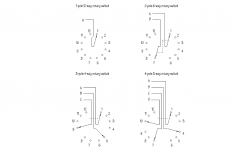
I found this diagram showing internals of switches and to me it looks, like your first suggestion - 2 pole 6 position switch is in fact, the correct switch as replacement. On board, all 4 center points are connected together and two wipers inside seems to be just one variant of this switch being adjust according to needs.
Link to switch tutorial and source for picture:
https://www.globalspec.com/learnmore/electrical_electronic_components/switches/rotary_switches
Attachments
He just needs one switch and 6 contacts. The others aren't connected. That's why I told him to shunt. They are already shunted on the board by the 3 sides square in the middle of the board. A simple 1 way 12 contacts would suffice with the stop tab placed on the 7th position..
Pay also attention of the shaft position, if it is D shaped.
Pay also attention of the shaft position, if it is D shaped.
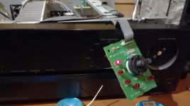
Yesterday evening got two 2P6P switches in case I break one. Opened one and removed the stop pin, bent the connection pints to fit the board, shortened and shaped the shaft, joined the poles and soldered it on. Issue was indeed, with the switch - new one works like a charm! (I had a bit of doubt because I cleaned the original switch two times and while it improved a little, issue remained - started to think relays are going bad).
Thank you Mooly and MAAC0, - if I could, I would buy you two a beer!
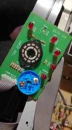
*picture with new switch in place attached.
Thank you Mooly and MAAC0, - if I could, I would buy you two a beer!
*picture with new switch in place attached.
Attachments
Last edited:

- Status
- This old topic is closed. If you want to reopen this topic, contact a moderator using the "Report Post" button.
- Home
- Design & Build
- Parts
- Kenwood KA-5090R input selector replacement