Hello to all.
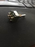
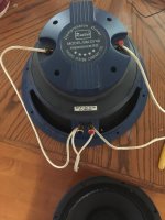
I am in the process of mounting two 12" full-range speakers (P-Audio BM12CX38) into their boxes. The tweeters are within the woofers, so there are two sets of contacts. No crossovers. But the design does entail three capacitors for each speaker, selectable by the M2020 toggle switch. My speaker wire goes from the amp to the woofer's contacts. Then a jumper connects the woofer negative to the tweeter negative. I understand that the jumper from the woofer positive to the tweeter positive is to be interrupted by the switch. The switch has three positions and I have three different capacitors to be selected by the switch. I do not know how to do the wiring of this switch. I had anticipated that each pair of contacts on the switch controlled a capacitor, but when I did a continuity test I found no continuity within the pairs. Instead, I found continuity between adjacent contacts. So I am quite confused. I have attached a photo of the switch. Any help would be much appreciated.
I am in the process of mounting two 12" full-range speakers (P-Audio BM12CX38) into their boxes. The tweeters are within the woofers, so there are two sets of contacts. No crossovers. But the design does entail three capacitors for each speaker, selectable by the M2020 toggle switch. My speaker wire goes from the amp to the woofer's contacts. Then a jumper connects the woofer negative to the tweeter negative. I understand that the jumper from the woofer positive to the tweeter positive is to be interrupted by the switch. The switch has three positions and I have three different capacitors to be selected by the switch. I do not know how to do the wiring of this switch. I had anticipated that each pair of contacts on the switch controlled a capacitor, but when I did a continuity test I found no continuity within the pairs. Instead, I found continuity between adjacent contacts. So I am quite confused. I have attached a photo of the switch. Any help would be much appreciated.
Attachments
But the design does entail three capacitors for each speaker, selectable by the M2020 toggle switch.
My speaker wire goes from the amp to the woofer's contacts.
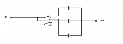
That's a standard 3 position (center off) DPDT switch. It's likely that the smaller capacitor
is always connected (in the center position), and the others are selected to be in parallel
with it (one at a time) by switching to one end or the other. Something like this diagram,
using just one side of the switch. Offhand, I don't see how to select each of the three
capacitors individually just with that switch.
Attachments
Last edited:
Chris, Rayma
Thank you for the quick responses. The M2020 switch that I have indicates 'On' three times (next to each pair of contacts). It may be difficult to see in the attached photo, but on the side of the switch the word, 'On' seems to clearly indicate that any position is live. And, indeed, the designer of my set-up included three caps. Does the foregoing change anything in the wiring diagram you have posted? Thank you for your attention.
Thank you for the quick responses. The M2020 switch that I have indicates 'On' three times (next to each pair of contacts). It may be difficult to see in the attached photo, but on the side of the switch the word, 'On' seems to clearly indicate that any position is live. And, indeed, the designer of my set-up included three caps. Does the foregoing change anything in the wiring diagram you have posted? Thank you for your attention.
Attachments
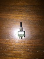
The M2020 switch that I have indicates 'On' three times (next to each pair of contacts).
on the side of the switch the word, 'On' seems to clearly indicate that any position is live.
Ok, the ON-ON-ON type does connect alternate pairs in the middle position.
Guitar Wiring Explored – Switches Part 3 | Seymour Duncan
So maybe there is a way to connect the switch to select just one of the three
capacitors at a time. Right now I can't figure it out, though.
Last edited:
Hi ALDEN,
I guess he had to make things difficult. I have seen a SP3P switch before and the wiring was really strange. I had to map it out with an ohmmeter and I decided to never try that again. The wiring for the capacitor would have been much easier if the switch was a simple ON-OFF-ON type. The smallest capacitor remains in circuit all the time, and the next larger values each go to a contact on the switch. The moving contact goes to one side of the smallest capacitor and the other two capacitors connect to the other side of the smallest one. I don't know if I just confused you or not.
If the kit has a pictorial on how to connect these capacitors up, follow it and don't try to figure it out. What are the three capacitor values?
-Chris
The switch I saw looked like a DPDT, but the positions were a mix of
single switch connections. It was very weird.
Actually this type is new to me, it looks like guitar people use them a lot.
Believe me, one encounter is enough with these darned things. I won't ever order
another one unless I'm replacing an existing one.
And there are two types of ON-ON-ON switches, one being the mirror image of the other.
Gentlemen,
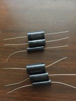
The three caps are marked:
"Dayton MPT 3.0uF 250V 5% AUDIO GRADE." ...2.0uF....1.0uF.
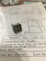
No wiring diagram accompanied the kit. I found the FaceBook page of David Dicks' Common Sense Audio and I sent him a message asking for wiring instruction, but his response is yet to come to hand.
I have no particular affinity for this switch. When I tested for continuity and found myself confused, I figured I would wire up the caps using a more 'simple' switching configuration. I am not versed in electronics as you guys- even the wiring diagram you guys gave me has me 'studying' it. I need something like an 'Idiot's Guide.' Anyway, if I recall correctly from my independent study of basic electronics, the caps have no positive or negative side, and I should have no issue in wiring simple switching for them and putting them between the woofer's positive and the tweeter's positive. Right? I appreciate the help, guys.
The three caps are marked:
"Dayton MPT 3.0uF 250V 5% AUDIO GRADE." ...2.0uF....1.0uF.
No wiring diagram accompanied the kit. I found the FaceBook page of David Dicks' Common Sense Audio and I sent him a message asking for wiring instruction, but his response is yet to come to hand.
I have no particular affinity for this switch. When I tested for continuity and found myself confused, I figured I would wire up the caps using a more 'simple' switching configuration. I am not versed in electronics as you guys- even the wiring diagram you guys gave me has me 'studying' it. I need something like an 'Idiot's Guide.' Anyway, if I recall correctly from my independent study of basic electronics, the caps have no positive or negative side, and I should have no issue in wiring simple switching for them and putting them between the woofer's positive and the tweeter's positive. Right? I appreciate the help, guys.
- Status
- This old topic is closed. If you want to reopen this topic, contact a moderator using the "Report Post" button.
- Home
- Design & Build
- Parts
- How to wire M2020 capacitor switch