love it - thanksThe trick is therefore to optimize the FET and the circuit resistance so that noise, bandwidth and distortion are all in an optimal place relative to the circuit requirements. If you do that, it is not difficult to get distortion below -100dB, and much better if you’re clever.
")
love it - thanks
I prefer 2x2N7002 in anti-series configuration (AC-switch) feeding a virtual ground - i.e. inverting input of an operational amplifier. These MOSFETS are available and low cost, on-resistance is small and distortion should be small as well (never measured THD of this application). Using a slow control signal switching clicks can be reduced to diminishing small levels.
Do a search for CMOS transmission gates. CD4052 is a useful configuration. (3x 4016/4066) .
I use the 74HC4051 in a USB oscilloscope.
Its runs off +/- rails which is good for audio.
Is controlled by TTL levels.
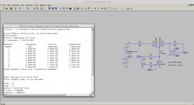
According to this LTspice simulation very low THD is possible
Looking a bit closer I think
a/ simulating 10kHz would be worthwhile and
b/ the harmonic spectrum looks pretty nasty ie; you have dominant H5 / H7 / H9
Ideally you are looking for H2 / H3 and nothing much else. Yes there is the
argument that at these levels it's inconsequential but factoring the likely
degradation of distortion as frequency rises and sim to reality difference it's
worth chasing very idealistic numbers with the sim.
Terry
This was a quick an dirty sim I did within 5 minutes. There might be some room for improvement. Please note that audio level was 20Vpp.Looking a bit closer I think
a/ simulating 10kHz would be worthwhile and
b/ the harmonic spectrum looks pretty nasty ie; you have dominant H5 / H7 / H9
Ideally you are looking for H2 / H3 and nothing much else. Yes there is the
argument that at these levels it's inconsequential but factoring the likely
degradation of distortion as frequency rises and sim to reality difference it's
worth chasing very idealistic numbers with the sim.
Terry
The normalized level of hl5, h7 is <2ppm - I call this a very low distortion.
Last edited:
Just for my amusement, I constructed the switch as presented a couple of posts ago, using Real Components™. Testing on the Audio Precision test set suggested that the worst distortion in the entire audio band happens at (roughly) 20kHz. I used 2N7000 FETs (as they were all I had today. Testing at several spot frequencies showed that there was essentially no measurable distortion - this could be a winning approach!
If you look at the datasheet of something like a 74HC4066, you will see some abrupt discontinuities in the resistance curve at just over one volt from either rail. To use one of these devices, you need to avoid these points at low signal levels. It doesn't matter so much at musical peaks.Looking a bit closer I think
a/ simulating 10kHz would be worthwhile and
b/ the harmonic spectrum looks pretty nasty ie; you have dominant H5 / H7 / H9
.....
Does the simulation impedance curve look anything like the data sheet?
well done!Just for my amusement, I constructed the switch as presented a couple of posts ago, using Real Components™. Testing on the Audio Precision test set suggested that the worst distortion in the entire audio band happens at (roughly) 20kHz. I used 2N7000 FETs (as they were all I had today. Testing at several spot frequencies showed that there was essentially no measurable distortion - this could be a winning approach!
I used CD4052 in a car stereo unit that was excellent. I see no reason that 2 x cd4052 at 18v both channels paralleled for left and right would not be outstanding.
1 chip for each channel.
Unfortunately, I find that the basic 4000-series CMOS switches add noticeable distortion. I've used them for switching Pre Fade Listen in disco mixers, but I wouldn't consider using them in a critical programme path.
Just for my amusement, I constructed the switch as presented a couple of posts ago, using Real Components™. Testing on the Audio Precision test set suggested that the worst distortion in the entire audio band happens at (roughly) 20kHz. I used 2N7000 FETs (as they were all I had today. Testing at several spot frequencies showed that there was essentially no measurable distortion - this could be a winning approach!
Would you provide some measurement plots of the circuit?
The results depend on the circuitry around. For lowest THD keep voltage excursions related to ground as small as possible.Unfortunately, I find that the basic 4000-series CMOS switches add noticeable distortion. I've used them for switching Pre Fade Listen in disco mixers, but I wouldn't consider using them in a critical programme path.
For that reason switching into a virtual ground summing node is superior to simple hi-impedance voltage switching.
I do not use 4000er gates specially because of their charge injection that causes audible glitches. And as you cannot slow down switching speed there is nothing you can do about it.
I used cd4066 in a 10 bit volume controller for tape recording mid 80's. I used a 15 volt supply split at 7.5v for the 2 op amps and 4066's. It does a wonderful job as I could not hear any audible difference now or then, when my hearing was much better.
47k drive resistors removed switch noise to op amp noise levels.
47k drive resistors removed switch noise to op amp noise levels.
Who says that? Are the contacts in a pair made of different materials?Don't use reed releays. They have thermal voltage on their contacts.
Best regards!
Unfortunately it's not Facebook to give a big LIKE for this questionWho says that? Are the contacts in a pair made of different materials?
Best regards!
There are lots of overstated remarks in the audio world...The first Phillips cd players and some of the very good ones , had reed relays in the signal path, many of the best amplifiers out there used reed relays too...It is possible to slow down the switching of CD4006 - type switches to pretty must cure any switching noise.
But because those switches have on resistance which rises with voltage you must chose the topology and impedance levels carefully for best results.
(It is not the absolute R that is the problem, but the variation. A 100 ohms switch is fine as long as the 100 ohm is constant).
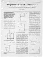
I have done quite a lot of investigations there and an article published at the time in Wireless World, see attached page 1. The full article is 5Mb so cannot attach it, but send me a PM and I will send you the article.
Edit: I made a quick page on my website so it can be downloaded directly A solid state switched attenuator | Linear Audio NL
Jan
But because those switches have on resistance which rises with voltage you must chose the topology and impedance levels carefully for best results.
(It is not the absolute R that is the problem, but the variation. A 100 ohms switch is fine as long as the 100 ohm is constant).
I have done quite a lot of investigations there and an article published at the time in Wireless World, see attached page 1. The full article is 5Mb so cannot attach it, but send me a PM and I will send you the article.
Edit: I made a quick page on my website so it can be downloaded directly A solid state switched attenuator | Linear Audio NL
Jan
Attachments
Last edited:
- Status
- This old topic is closed. If you want to reopen this topic, contact a moderator using the "Report Post" button.
- Home
- Design & Build
- Parts
- Best electronic switch for audio signals-logic drive