Quad or Series/Parallel or Series/Parallel Quad resistors are a combination of resistors sometimes used to reduce distortion. They aren't very well known and a bit odd, so I thought I would start a thread to talk about them. There isn't one name that is used consistently, so I will call them Quads.
Although they can be used to reduce distortion in any circuit, I believe they are especially useful as power resistor replacements in audio circuits. More about that later.
Description
A Quad resistor replaces a single resistor in a circuit. The Quad is 4 resistors of the same value as the single resistor that are arranged in 2 series strings of 2 resistors each. The strings are connected in parallel. The result is a combination with the same resistance as the single resistor and that has some interesting advantages over the single resistor.
Specifically, the Quad has lower distortion (-12 dB) and 4 times the power capacity of a single resistor using the same resistors in the Quad. Of course, there is no rule that you have to use the same resistor type in the Quad, so that opens up possibilities for quieter resistors made with different technologies. To me, this is very interesting in the area of power resistors used in audio signal circuits.
For example, let's say you have an audio signal circuit with a resistor that dissipates 1.5 to 2W. For safety margin, a 4W resistor is chosen. The traditional choices are metal-Ox, thick film, or maybe wire wound. The Quad resistor opens up the possibility of using 4 thin film or foil 1W resistors.
So let's dig into the differences. The measured data shows that a Quad built with film/foil resistors have lower distortion, better heat transfer, lower current noise, and lower power distortion than a single metal-Ox, thick film, and wire wound resistor.
Distortion
The primary source of distortion in a resistor is the change in resistance as a function of voltage across the resistor. The change in the resistance changes the signal and that is distortion. This distortion is primarily 3rd harmonic (per the Groner paper linked below).
If you replace the single resistor with 4 identical resistors in series/parallel (2 strings of 2 resistors each in series and the strings in parallel), you end up with half the voltage across each resistor. The theory says that halving of the voltage reduces the overall distortion to ¼ of the original distortion. That represents approximately 12 dB reduction in distortion.
If you want to dig into the technical stuff, I will refer you to Samuel Groner's discussion under the “Main Oscillator Loop/Passive Components” in the link below. It's not terribly satisfying because he says, “it can be shown” at the critical point of discussing distortion, but I believe his information is correct because I have seen other discussions with the same answer.
http://www.nanovolt.ch/resources/low_distortion_oscillators/pdf/low_distortion_oscillator_design.pdf
Heat Transfer
Heat transfer is a function of the resistor design and implementation. Traditionally, power resistors in audio are axial, cylindrical, and spaced slightly above the pcb to allow air flow around the whole circumference. While this is good practice, it is not always enough. I have measured a 3W rated axial resistor mounted on a pcb as above that reached 70 deg C with at only 1W power across the resistor. In contrast, a Quad resistor in the same test reached 36 deg C. Heat transfer can be important.
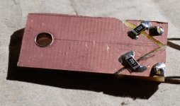
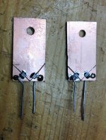
TO-220 style resistors have a big advantage. By being vertical with large surface area, they improve their heat transfer and their design makes it possible to add additional heat sinking. The Quad resistors shown in the pictures are also designed with large surface area, vertical orientation, and the ability to add heat sinking near the top. Note that these diy Quads are made using a 2 sided, copper clad board with hand cut traces and SMD resistors and copper leads. The board is the same on both sides with one resistor string on each side.
Current Noise
Per the reference linked below, thick film and metal-oxide resistors have measured current noise 2 to 3 orders of magnitude worse than a good ¼W metal film resistor. Specifically, several Caddock series and the popular Panasonic ERG 2W are measured in this test.
https://dcc.ligo.org/public/0002/T0900200/001/current_noise.pdf
Wire wound resistors are often very good for current noise, but have inductance issues. Some people like the low inductance versions, but personally I don't care for those either.
Power Distortion
Resistors have a thermal impedance (deg C/W) based on their design. Combine that with the TCR (temperature coefficient of resistance) and you get PCR (power coefficient of resistance) or Ohms/W.
If this were just DC, we would still get a change in resistance as a function of power and, of course, that change in resistance represents distortion. But music, is not DC. It is both AC and transient. When you introduce a varying signal, the resistor element changes temperature pretty quickly in response to changes in power, but the body of the resistor has additional mass and thermal resistance, so it takes some time to dissipate the heat generated by a change in power.
Some say that a resistor will change resistance in time with the music, at least with the lower frequencies. I'm not sure I buy that, but I do accept that music has loud and soft passages where high and low power is passed through power resistors and a varying power distortion will exist.
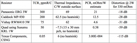
Here is an example based around a 0R33 resistor running at 2W. For the SMD resistors, 1W resistors in a Quad are shown. Surface temperature is used because that is quoted in datasheets. The Quad data was a measurement based on a hand cut pcb. All other data is from manufactures datasheets. See the table in the photos below.
Of course, the Caddock, the Quads, and the CSNG can use a heat sink and significantly reduce thermal impedance and PCR. For example, with a 3 C/W heatsink, the Caddock can get below -50 dB.
As you can see, the Quad is a big improvement over the Panasonic metal-Ox, Caddock thick film, and Vishay wirewound. Of course, the Z foil CSNG is better than all of them by a significant margin.
Sound Quality
All of this is just data and theory. I have tried Quads in two projects now and I find them to noticeably improve clarity when a Quad replaces a metal-Ox or thick film in the signal path. But please, try it yourself and make up your own mind.
Although they can be used to reduce distortion in any circuit, I believe they are especially useful as power resistor replacements in audio circuits. More about that later.
Description
A Quad resistor replaces a single resistor in a circuit. The Quad is 4 resistors of the same value as the single resistor that are arranged in 2 series strings of 2 resistors each. The strings are connected in parallel. The result is a combination with the same resistance as the single resistor and that has some interesting advantages over the single resistor.
Specifically, the Quad has lower distortion (-12 dB) and 4 times the power capacity of a single resistor using the same resistors in the Quad. Of course, there is no rule that you have to use the same resistor type in the Quad, so that opens up possibilities for quieter resistors made with different technologies. To me, this is very interesting in the area of power resistors used in audio signal circuits.
For example, let's say you have an audio signal circuit with a resistor that dissipates 1.5 to 2W. For safety margin, a 4W resistor is chosen. The traditional choices are metal-Ox, thick film, or maybe wire wound. The Quad resistor opens up the possibility of using 4 thin film or foil 1W resistors.
So let's dig into the differences. The measured data shows that a Quad built with film/foil resistors have lower distortion, better heat transfer, lower current noise, and lower power distortion than a single metal-Ox, thick film, and wire wound resistor.
Distortion
The primary source of distortion in a resistor is the change in resistance as a function of voltage across the resistor. The change in the resistance changes the signal and that is distortion. This distortion is primarily 3rd harmonic (per the Groner paper linked below).
If you replace the single resistor with 4 identical resistors in series/parallel (2 strings of 2 resistors each in series and the strings in parallel), you end up with half the voltage across each resistor. The theory says that halving of the voltage reduces the overall distortion to ¼ of the original distortion. That represents approximately 12 dB reduction in distortion.
If you want to dig into the technical stuff, I will refer you to Samuel Groner's discussion under the “Main Oscillator Loop/Passive Components” in the link below. It's not terribly satisfying because he says, “it can be shown” at the critical point of discussing distortion, but I believe his information is correct because I have seen other discussions with the same answer.
http://www.nanovolt.ch/resources/low_distortion_oscillators/pdf/low_distortion_oscillator_design.pdf
Heat Transfer
Heat transfer is a function of the resistor design and implementation. Traditionally, power resistors in audio are axial, cylindrical, and spaced slightly above the pcb to allow air flow around the whole circumference. While this is good practice, it is not always enough. I have measured a 3W rated axial resistor mounted on a pcb as above that reached 70 deg C with at only 1W power across the resistor. In contrast, a Quad resistor in the same test reached 36 deg C. Heat transfer can be important.
TO-220 style resistors have a big advantage. By being vertical with large surface area, they improve their heat transfer and their design makes it possible to add additional heat sinking. The Quad resistors shown in the pictures are also designed with large surface area, vertical orientation, and the ability to add heat sinking near the top. Note that these diy Quads are made using a 2 sided, copper clad board with hand cut traces and SMD resistors and copper leads. The board is the same on both sides with one resistor string on each side.
Current Noise
Per the reference linked below, thick film and metal-oxide resistors have measured current noise 2 to 3 orders of magnitude worse than a good ¼W metal film resistor. Specifically, several Caddock series and the popular Panasonic ERG 2W are measured in this test.
https://dcc.ligo.org/public/0002/T0900200/001/current_noise.pdf
Wire wound resistors are often very good for current noise, but have inductance issues. Some people like the low inductance versions, but personally I don't care for those either.
Power Distortion
Resistors have a thermal impedance (deg C/W) based on their design. Combine that with the TCR (temperature coefficient of resistance) and you get PCR (power coefficient of resistance) or Ohms/W.
If this were just DC, we would still get a change in resistance as a function of power and, of course, that change in resistance represents distortion. But music, is not DC. It is both AC and transient. When you introduce a varying signal, the resistor element changes temperature pretty quickly in response to changes in power, but the body of the resistor has additional mass and thermal resistance, so it takes some time to dissipate the heat generated by a change in power.
Some say that a resistor will change resistance in time with the music, at least with the lower frequencies. I'm not sure I buy that, but I do accept that music has loud and soft passages where high and low power is passed through power resistors and a varying power distortion will exist.
Here is an example based around a 0R33 resistor running at 2W. For the SMD resistors, 1W resistors in a Quad are shown. Surface temperature is used because that is quoted in datasheets. The Quad data was a measurement based on a hand cut pcb. All other data is from manufactures datasheets. See the table in the photos below.
Of course, the Caddock, the Quads, and the CSNG can use a heat sink and significantly reduce thermal impedance and PCR. For example, with a 3 C/W heatsink, the Caddock can get below -50 dB.
As you can see, the Quad is a big improvement over the Panasonic metal-Ox, Caddock thick film, and Vishay wirewound. Of course, the Z foil CSNG is better than all of them by a significant margin.
Sound Quality
All of this is just data and theory. I have tried Quads in two projects now and I find them to noticeably improve clarity when a Quad replaces a metal-Ox or thick film in the signal path. But please, try it yourself and make up your own mind.
Attachments
In most cases a little inductance does no harm to an audio circuit so wirewounds can be used.
Simply replacing resistors by 4-resistors could lead, in some cases, to stability problems due to an increase in stray capacitance.
There are circumstances in which this change could be beneficial. In most cases it will achieve nothing, except a warm glow inside the person who did it. In a few cases it will do harm. So just like most other tweaks, then.
And takes up four times the pcb room !
Just for clarification, It takes us about the same room on a pcb as any TO-220 device.
In most cases a little inductance does no harm to an audio circuit so wirewounds can be used.
Simply replacing resistors by 4-resistors could lead, in some cases, to stability problems due to an increase in stray capacitance.
First of all, if you are happy with wirewound resistors, then enjoy. As I said in the first post, my dislike for the sound of wirewound resistors is personal and subjective.
That said, a couple of points. Many amplifiers use small value power resistors similar to the example shown in the table in post 1. In my opinion, this is the condition that you need to be most careful of inductance. The rising impedance of inductance can exceed the low impedance of the resistance and change the signal. Unfortunately, the wirewound resistor used in the example, Vishay RWM410, doesn't give any inductance in it's datasheet, so I can't calculate the frequency where it exceeds the resistance. I fully admit that it may be well out of the audio bandwidth.
I also agree that large area of the Quad could, in theory, pick up airborne EMF through it's capacitance. That hasn't been a problem so far, but it is a theoretical risk. Note that the impedance to ground of both sides of the Quad is essentially equal. In fact, you can electrically connect the two sides of the tall heat sink surface without affecting the performance of the combined resistor. This should resolve most stray capacitance issues.
On the other hand, for the example above, power distortion is running at an estimated -31 dB for the wirewound, RWM410. That is primarily due to the heat rejection of the resistor.
Last edited:
You must have some very nice test equipment to measure resistor distortion.
+1
Plus incredible ears to hear it.
Er, nope....
And takes up four times the pcb room !
...
An array of 4 or 6 cheap mox 0.6-watters mounted vertically will take less PCB estate than a single 2 or 3-watter and would also be more rugged mechanically.
Price and availability ... may vary. If you buy bulk, an array may be cheaper by far.
An array will look "cheaper" as well - if you care for the looks of the product, so ...
Slightly More Traditional
In honor of DF96, the more traditional way of looking at this issue would be to use two resistors in series, for example wirewound each at half the value of the original resistor.
-low current noise - check
-let's assume no inductance issues
-because each resistor is at half voltage, voltage distortion =-12 dB
-each resistor is at half the power, so power distortion is -6 dB from a single resistor.
In my Post #1 example, the wirewound Vishay RWM410 would have power distortion at -37 dB.
Overall, of the traditional power resistors, this is an excellent option.
Of course, you could also use two resistors in parallel with double the value. It would have all the benefits of the series example above, except for the voltage distortion advantage.
Naturally, two resistors in either series or parallel, it will require more pcb space.
I have looked at the calculations in post 1. The arithmetic looks OK, but the conclusions may be misleading. A 'distortion' figure of -18dB sounds horrifying, but this is not non-linear distortion. It is merely a small shift in a resistor value due to the signal envelope. This may or may not affect the audio. Whether it responds to bass too depends on the thermal time constant of the resistive element, which the calculation does not address. Typically, a smaller resistor will have a bigger effect. Given the choice between a big wirewound (which may respond to signal envelope) and four ordinary resistors (which may respond to bass) I would choose the wirewound. Two ways to check: detailed measurements, detailed multiphysics simulation.
I have looked at the calculations in post 1. The arithmetic looks OK, but the conclusions may be misleading. A 'distortion' figure of -18dB sounds horrifying, but this is not non-linear distortion. It is merely a small shift in a resistor value due to the signal envelope. This may or may not affect the audio. Whether it responds to bass too depends on the thermal time constant of the resistive element, which the calculation does not address. Typically, a smaller resistor will have a bigger effect. Given the choice between a big wirewound (which may respond to signal envelope) and four ordinary resistors (which may respond to bass) I would choose the wirewound. Two ways to check: detailed measurements, detailed multiphysics simulation.
Fair enough. The -18 dB has a lot to do with the small resistance value I chose, so I am definitely using a worst case. In a situation where the resistor is 1k, this isn't even worth discussing. But that small shift in resistance isn't so small relative to the 330 mOhms of the example. So it will depend on the circuit whether the resistance of the small value resistor as significant effect on the output. I guess you could say that one reason for starting this thread is that power distortion in resistors or resistor noise and distortion isn't even considered most of the time and that there will be situations where you should at least check.
As for what kind of distortion and whether it affects audio, I can't give you an objective answer at this point. I suspect that is the same as voltage distortion which Groner describes as primarily 3rd harmonic. In future, I will attempt distortion measurement in a circuit, but the results will be largely circuit dependent.
Your point about the time constant of the resistive element is also worth considering. Unfortunately, there is little information available. But let's think about this a little.
I think we can assume that the thermal mass of the wirewound resistive element is a high percentage of the thermal mass of the total resistor and that's a good thing slowing down the change in resistance with power. Therefore, the wirewound should have less modulation in response to musical transients and variation than other resistors.
With wirewound, it's easy to use a higher wattage rating resistor. I could easily have used a 10W instead of a 3W in the example and moved the power distortion calculation in post 1 from -31 to -47 dB for the wirewound. That, combined with the less modulation discussed above would be an effective choice in a circuit where this resistor position could affect sound quality.
One of the interesting things about the Quad using some of today's power SMD resistors is that those resistors have been optimized to maximize heat rejection, much of it through the pcb. The Susumu KRL for example is a face down resistor with oversize pads on the long dimension so that heat in the resistive element has the shortest, lowest thermal resistance path to the pcb. So now you have a low thermal mass or fast heating resistive element matched with fast thermal transfer to the heat sink (PCB). With my handmade pcb acting like a heatsink of about 7.5 C/W, the resistors are kept relatively low temperature. A different approach than the wirewound, but an interesting one.
As a side note, there are a lot of power SMD that are thick film and, personally, I wouldn't choose them. Thick film is relatively poor for current noise and others have measured higher distortion in specific circuits using thick film SMD resistors.
The main point of this thread is to spark the discussion of how power resistors are different than ordinary signal resistors. It is also to introduce the Quad approach which I feel is an interesting alternative. I understand that you prefer wirewound, have valid reasons for your choice, and I respect that choice.
Attachments
If your curious or adventurous may I introduce you to Powertrons.
Am using it now on my ML Odyssey. All I can say is compared to wirewounds
be it Mills, Ohmite or M Resist Supreme, it is heads above them, very smooth
& transparent . I wouldn’t dare say it adds nothing to the sound but as compared
to wire wounds, it clearly adds nothing.
Cheers
Am using it now on my ML Odyssey. All I can say is compared to wirewounds
be it Mills, Ohmite or M Resist Supreme, it is heads above them, very smooth
& transparent . I wouldn’t dare say it adds nothing to the sound but as compared
to wire wounds, it clearly adds nothing.
Cheers
Interesting. I was not familiar with them. I looks like they have F and U series which are foil types and K and N series which are thick film. The foil types are likely similar to the texas components CSNG listed in the example, post 1. I am guessing that they are expensive, yes?
-because each resistor is at half voltage, voltage distortion =-12 dB
-each resistor is at half the power, so power distortion is -6 dB from a single resistor.
You're mixing dB's here. The primary distortion is from power (temperature coefficient) a function of V squared. The signal of interest is the voltage so the -12dB is the only relevant number.
You're mixing dB's here. The primary distortion is from power (temperature coefficient) a function of V squared. The signal of interest is the voltage so the -12dB is the only relevant number.
My mistake, at least in part. I should have used the square of the ratio in the power distortion calculations. But let's test my understanding. I am leaning on the Groner paper for theory. On page 19 of the paper, he talks about using the Quad and metal film resistors in his project. He refers to the Quad and the -12 dB as only relating to the voltage coefficient of the resistor, that is, the voltage coefficient is the change in resistance as a function of voltage at a constant temperature. He then goes on to talk about the need to include distortion from the power coefficient due to temperature change. He is saying that the voltage distortion and power distortion are separate and independent.
If that's true, then I should correct the power distortion numbers. The new calculation would be 20Log((delta R from temp @ a given power/nominal R)^2). Power distortion for the resistor itself in my post 1 example would be;
Metal Ox (Panasonic) -36 dB
Thick film (Caddock) -45 dB
Wirewound (Vishay) -62 dB
diy Quad SMD (Susumu) -106 dB
Z foil (texas components) -187 dB
More reasonable numbers. Still showing that, depending on how the change in resistance of the single resistor affects the specific circuit, there are noticeable differences in power distortion, plus voltage distortion and current noise differences remain. By the way, I also found an error in the Z foil calculation. The datasheet quoted a number that was using a heatsink. I corrected for the resistor in free air.
Any more mistakes? I am prone to them
")
Last edited:
- Status
- This old topic is closed. If you want to reopen this topic, contact a moderator using the "Report Post" button.
- Home
- Design & Build
- Parts
- Quad or Series/Parallel Resistors as an alternative to traditional power resistors